
Channeling gas flow tube

a gas flow tube and channeling technology, applied in the field of tubes, can solve the problems of reducing efficiency, reducing efficiency, affecting the effect of drag, etc., and achieve the effect of increasing the magnetic flux, increasing the electric current, and increasing the forward momentum

Inactive Publication Date: 2012-11-01
PARALLAXIAL INNOVATION
View PDF2 Cites 27 Cited by
  • Summary
  • Abstract
  • Description
  • Claims
  • Application Information

AI Technical Summary

Benefits of technology

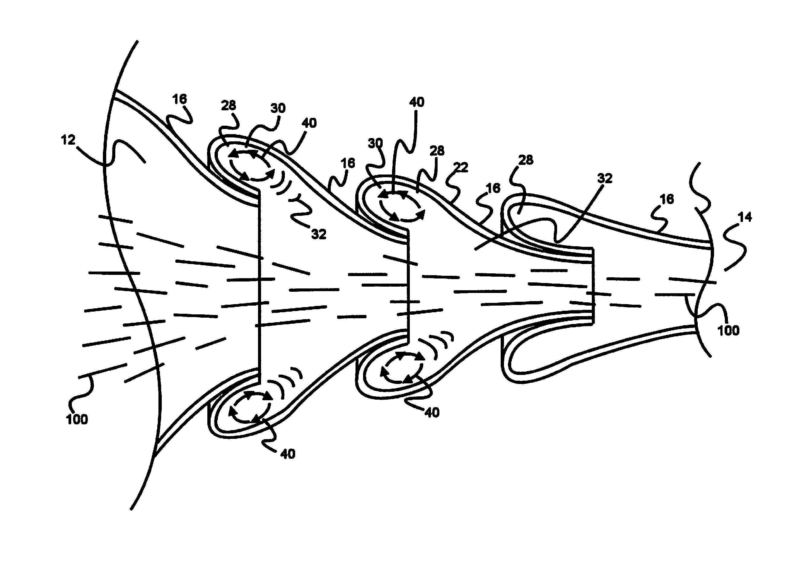
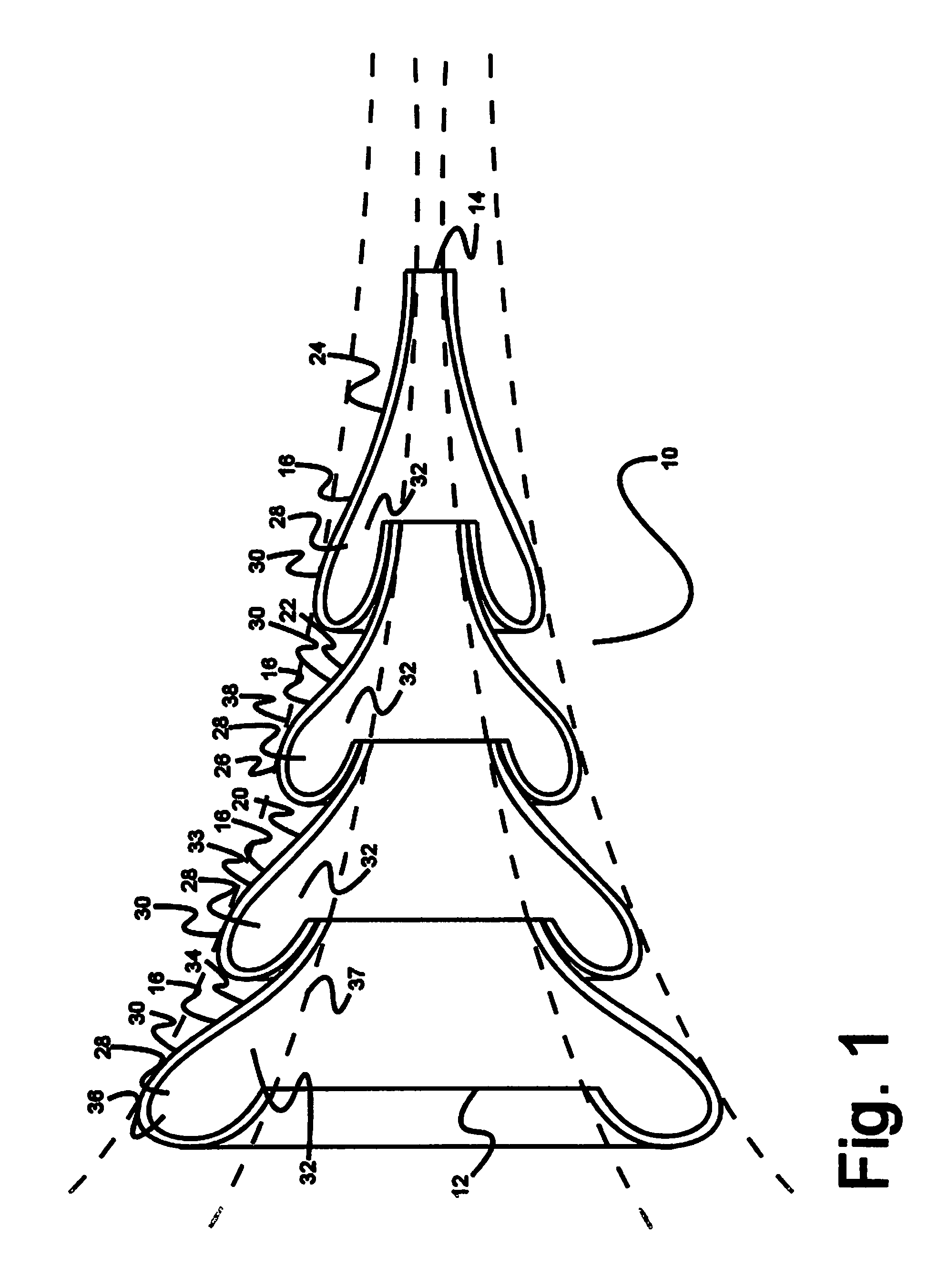
"The invention is a tube that uses guides to modify the flow of gas inside it. The guides are arranged in a series, with each guide smaller than the previous one. This results in a funnel-shaped tube that helps to smoothly transition the gas flow and reduce noise and shock waves. The guides also create a cavity that allows for fluid dynamic interactions, which further optimize the flow and reduce heat and noise generation. The tube can be used as an automotive exhaust pipe or a chute for separating objects or particles from the gas flow. When installed, it provides an effective muffler without using conventional baffles and silencers. The dimensions of the guides can also be changed to change the engine exhaust sound. Overall, the invention helps to improve the efficiency and performance of the engine."

Problems solved by technology

Other examples where fluid flow may have deleterious effects include, but are not limited to, firearms (shock waves in barrels reduces kinetic energy of projectile fired and causes extreme noise), projectile flight (drag on projectile reduces range and may destabilize flight), aircraft wings and other airfoils (drag reduces efficiency and turbulence may adversely impact left generated by an airfoil), terrestrial vehicles (drag reduces efficiency), and jet engines (again, drag from fluid flows reduces efficiency).

Method used


Image

  • Channeling gas flow tube
  • Channeling gas flow tube
  • Channeling gas flow tube

Examples


Embodiment Construction

[0029]The inventor has conceived, and reduced to practice, a channeling gas flow tube that addresses the challenges and problems in the art outlined above. Various techniques will now be described in detail with reference to a few example embodiments thereof, as illustrated in the accompanying drawings. In the following description, numerous specific details are set forth in order to provide a thorough understanding of one or more aspects and / or features described or referenced herein. However, it will be apparent to one skilled in the art, that one or more aspects and / or features described or referenced herein may be practiced without some or all of these specific details. In other instances, well known process steps and / or structures have not been described in detail in order to not obscure some of the aspects and / or features described or reference herein.

[0030]One or more different inventions may be described in the present application. Further, for one or more of the inventions ...


PUM


Abstract

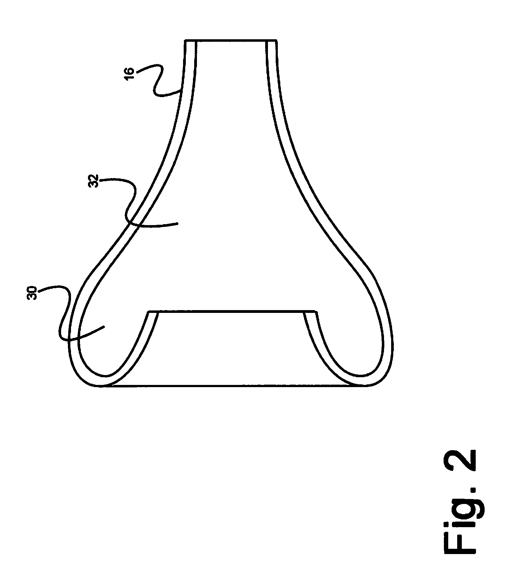
A tube for moving gas between an entry end into which gas is introduced and an exit end through which gas exits the tube, the tube comprising a plurality of adjoining adjacent□ guides, each guide comprising an outer half of a smoothly-curved, modified torus, and an outer rigid tube wall. Each guide forms an internal cavity with a cavity mouth opening into an inner portion of the tube, the cavities shaped such that a vortex forms within each of the cavities as gas passes through the tube, and the flow of fluid in the tube is unidirectional and axial from the entry end to the exit end.

Description

RELATED APPLICATIONS[0001]This application is a continuation-in-part of U.S. patent application Ser. No. 12 / 238,253, titled “CHANNELING GAS FLOW TUBE”, filed on Sep. 25, 2008 and issuing on Jul. 3, 2012 as U.S. Pat. No. 8,210,309, the entire specification of which is incorporated herein by reference.BACKGROUND OF THE INVENTION[0002]1. Field of the Invention[0003]This invention pertains to tubes through which a fluid may move, and more particularly, to such a tube that channels gases, and articles suspended in a gas flow, centrally or axially down the tube.[0004]2. Discussion of the State of the Art[0005]Backpressure in engine exhausts is a well-known phenomenon that robs energy from the engine. Mufflers and catalytic converters contribute to the backpressure. It is a primary object of the present invention to provide a tube functional as an exhaust pipe that reduces backpressure and reduces or eliminates the need for a muffler.[0006]More generally, many devices known in the art rely...

Claims


Application Information

Patent Timeline
Patent Type & Authority Applications(United States)
IPC IPC(8): F41A21/30F01N13/00F15C1/16
CPCF01N1/026F01N13/082F01N2470/20F16L9/22F01N2490/155F01N2490/16F41A21/30F01N2470/24Y10T137/2093
Inventor SCHLOSSER, THOMAS GEORGE
Owner PARALLAXIAL INNOVATION
Learn More