
Ink jet ink and ink jet recording method

Active Publication Date: 2012-10-18
KONICA MINOLTA IJ TECHNOLOGIES INC
View PDF2 Cites 34 Cited by
  • Summary
  • Abstract
  • Description
  • Claims
  • Application Information

AI Technical Summary

Benefits of technology

[0017]The present invention has been achieved in view of the above-described problems. It is an object of the present invention to provide an aqueous ink jet ink that exhibits low environmental load during image formation and can form a print image having high fineness without uneven density or pin holes, excellent glossiness and high friction resistance on a nonabsorbent recording medium. It is also an object of the present invention to provide an ink jet recording method using the ink.Solution to Problem
[0030]The present invention provides an aqueous ink jet ink that exhibits low environmental load during image formation and can form a print image having high fineness without uneven density or pin holes, excellent glossiness and high friction resistance on a nonabsorbent recording medium. The present invention also provides an ink jet recording method using the ink.

Problems solved by technology

This causes generation of a large amount of volatile organic compounds (VOC), which is nowadays a socially disputed issue.
In addition, odors and adverse safety effects on workers are concerned, and facilities, such as sufficient ventilation systems, for overcoming such concerns are required in use of the ink.
In addition, ink jet printers are required to be equipped with expensive ultraviolet light sources.
Accordingly, fields to which the ultraviolet curable ink jet inks can be applied are inevitably limited.
Furthermore, upon printing on glossy sheets, the glossiness is considerably lost at areas where the inks are applied, which makes it difficult to yield an image having high quality.
Unfortunately, recording media having poor absorbability, such as coated paper and resin films, have low surface energy in many cases and do not absorb typical aqueous inks.
Consequently, ink droplets landed on such a recording medium are repelled to generate pin hole in an image or unevenness in a solid portion, resulting in a decrease in image quality.
Another disadvantage is that the recording medium has no aqueus ink absorbency; this prolongs drying time and causes deposition of unabsorbed coloring materials on the recording medium, resulting in a decrease in image durability such as friction resistance.
However, addition of an excess amount of a surfactant causes precipitation of the surfactant after the ink dries, resulting in a decrease in image glossiness.
Although the use of an organic solvent having low surface tension does not cause precipitation, it does not increase the friction resistance.
In addition, many of the organic solvents having low surface tensions have high boiling points, causing poor ink drying characteristics.
Unfortunately, the results of investigation by the present inventors show that although the method described in PTL 1 prevents weak repelling to some extent, effects on preventing strong repelling and pin holes are still low.
Consequently, the method described in PTL 1 is still insufficient for preventing formation of defected images (e.g., unevenness or pin holes).
Unfortunately, the results of investigation by the present inventors show that although a certain improvement is observed in a region to which a small amount of ink droplets is applied, repelling and pin holes occur in a region, such as solid printing, where a large amount of ink droplets is applied and that the resulting image has a large difference in glossiness between the white surface portion of the base material and the image portion to give discomfort feeling in visual observation.
Unfortunately, the results of investigation by the present inventors show that the wettability of an aqueous ink to a nonabsorbent recording medium is improved by the addition of a surfactant, but an improvement in image quality, in particular, unevenness and pin holes in solid portions, is still insufficient.
On the contrary, the addition of a surfactant further decreases image quality in some cases.
Thus, in the case of recording on a nonabsorbent recording medium, in particular, on a vinyl chloride sheet, with an aqueous ink, it is significantly difficult to form an image having high fineness comparable to that of an image formed with a solvent ink.

Method used


Image

  • Ink jet ink and ink jet recording method
  • Ink jet ink and ink jet recording method
  • Ink jet ink and ink jet recording method

Examples


example 1

Synthesis of Binder Resin

Synthesis of Binder Resin P-1

[0133]Into a flask equipped with a drop funnel, a nitrogen gas inlet tube, a reflux condensing tube, a thermometer, and a stirrer was placed 50 parts of methyl ethyl ketone, which was then heated to 75° C. with nitrogen bubbling. A mixture of a monomer composition (9.0 parts of methacrylic acid, 78 parts of methyl methacrylate, 6.5 parts of n-butyl acrylate, and 6.5 parts of 2-ethylhexyl acrylate), 50 parts of methyl ethyl ketone, and 0.5 parts of an initiator (AIBN: 2,2′-azobisisobutyronitrile) was dropwise added to the flask over 3 hr from the drop funnel. The mixture was then heated under reflux for a further 6 hr. After cooling, the methyl ethyl ketone was distilled off by heating under reduced pressure to yield a copolymer resin.

[0134]Separately, a solution of dimethylaminoethanol was prepared by dissolving dimethylaminoethanol in 450 parts of deionized water in an amount of 1.05 times molar equivalent to (meth)acrylic acids...

example 2

[0163]Cyan inks C21 to C40 were prepared as in preparation of inks in Example 1 except that Joncryl 537J (manufactured by BASF Japan, Inc., styrene-acrylic resin emulsion) was used instead of binder resin P-1 and that JDX: Joncryl JDX-6500 (manufactured by BASF Japan, Inc., acrylic resin) was used instead of binder resin P-2, in cyan inks C1 to C20, and the resulting inks were evaluated.

[0164]Cyan inks C21 to C30 according to the present invention satisfied requirements (a) to (c) and formed highly glossy images without uneven density and pin holes. In contrast, cyan inks C31 to C40 in Comparative Examples did not satisfy any one of requirements (a) to (c) and did not form high-quality images.

example 3

Preparation of Pigment Dispersion

Preparation of Yellow Pigment Dispersion

[0165]To 60 parts of deionized water were added 10 parts of EFKA-4585 (solid content: 50%, manufactured by BASF Japan, Inc.) serving as a pigment dispersing agent and 10 parts of 1,2-hexanediol. To this solution, 15 parts of Levascreen Yellow G01 (manufactured by Lanxess Deutschland GmbH) was added, followed by premixing. The premix was subjected to dispersion treatment with a sand grinder loaded with 50 vol % of 0.5 mm zirconium beads to yield a yellow pigment dispersion having a pigment solid content of 15%.

Preparation of Magenta Pigment Dispersion

[0166]A magenta pigment dispersion was prepared as in preparation of the cyan pigment dispersion in Example 1 except that Pigment Red 122 (manufactured by Dainichiseika Color & Chemicals Mfg. Co., Ltd., CFR-321) was used as a magenta pigment instead of C.I. Pigment Blue 15:3 as the cyan pigment.

Preparation of Black Pigment Dispersion

[0167]To 60 parts of deionized wa...


PUM

PropertyMeasurementUnit
Percent by massaaaaaaaaaa

Abstract

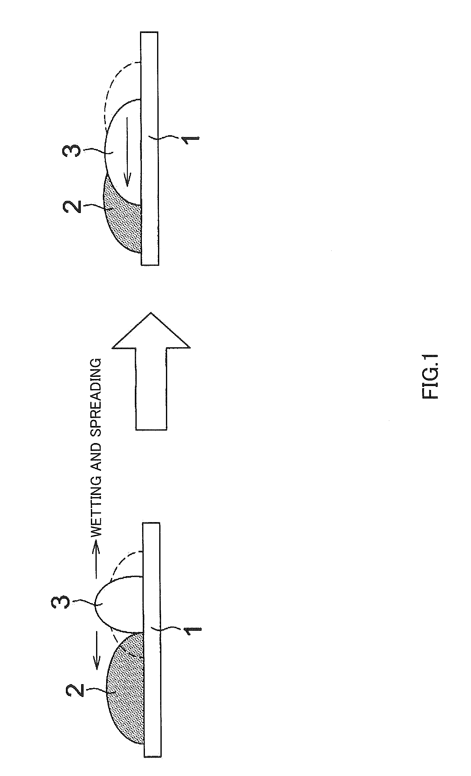
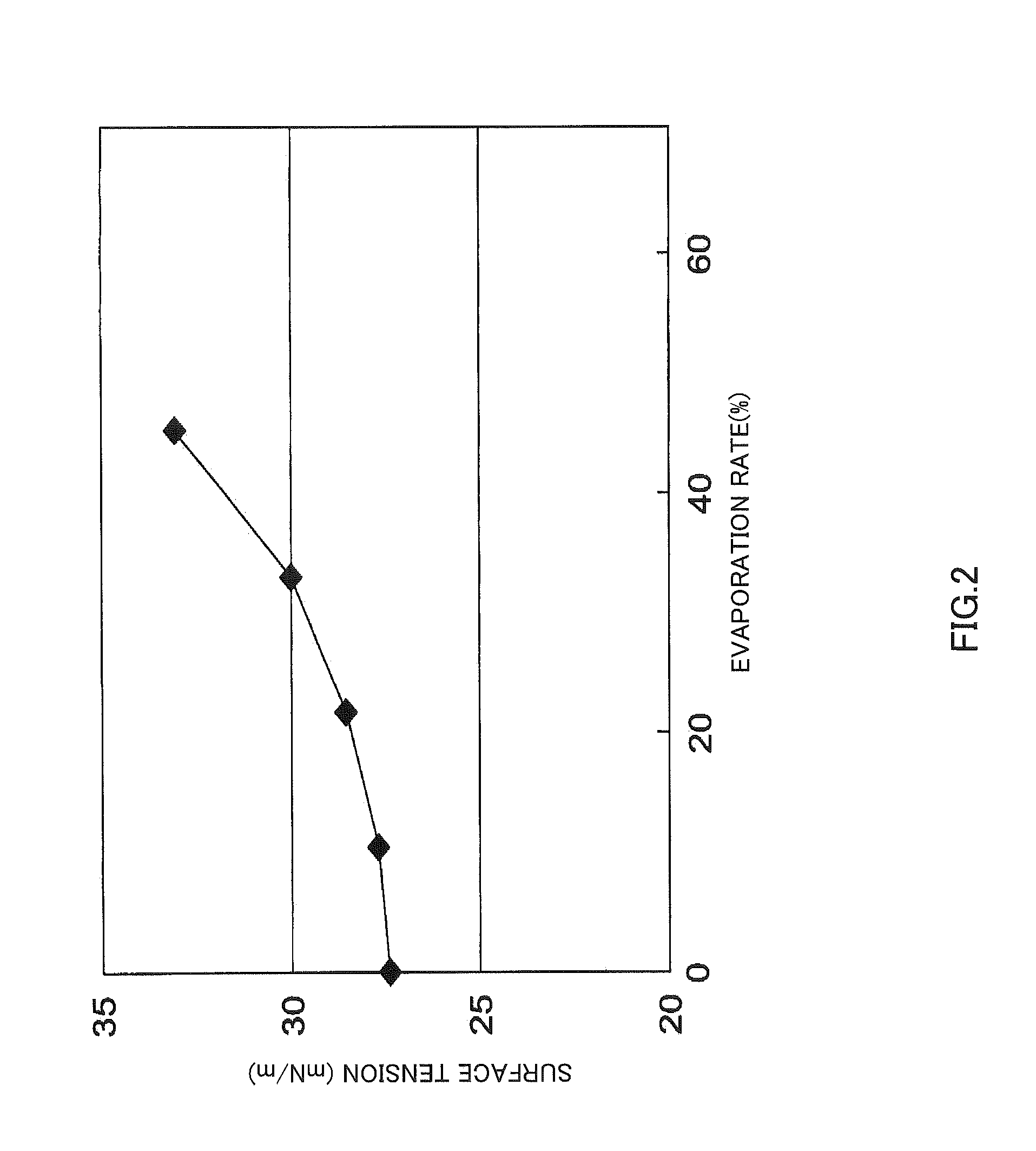
In an ink jet ink containing a pigment, a binder resin, water, an organic solvent, and a surfactant, the surface tension of the ink is in a region defined by γ0−γx≧1.0 (γ0: surface tension before evaporation, γx: surface tension at an evaporation rate X %) when the evaporation rate X of the ink is in a range of 0<X(%)≦20; the ink jet ink contains two or more organic solvents; and the content of an organic solvent of which the sum ΣSP of the hydrogen bonding term and the polarity term of the solubility parameter is 8 to 18 MPa1 / 2 is 30 mass % or more and less than 95 mass % of the total amount of the organic solvents; and the content of the surfactant is less than the critical micelle concentration of the surfactant.

Description

TECHNICAL FIELD[0001]The present invention relates to an aqueous ink jet ink that can record information on a recording medium having poor ink absorbability and relates to an ink jet recording method using the ink.BACKGROUND ART[0002]Ink jet inks for industrial use have been extensively developed so that the inks can be used in direct printing on recording media that hardly absorb inks, e.g., recording media having poor water absorbability such as resin- or clay-coated paper, recording media coated with resin components, or resin films themselves, as well as on paper and cloth having ink absorbability.[0003]Examples of ink jet inks satisfying such requirements include solvent ink jet inks containing organic solvents as vehicles and ultraviolet curable ink jet inks containing photopolymerizable monomers as their main components. In the solvent ink jet inks, the solvents are evaporated, and most of the solvent components dissipate in the air. This causes generation of a large amount o...

Claims


Application Information

Patent Timeline
IPC IPC(8): B41J2/015C08K5/20C09D11/10B41J2/01B41M5/00B41M5/50B41M5/52C09D11/00C09D11/322C09D11/326C09D11/38
CPCC09D11/322
Inventor TAKAKU, YUSUKEMORI, HISASHI
Owner KONICA MINOLTA IJ TECHNOLOGIES INC
Learn More