
Organic luminescent element

Inactive Publication Date: 2012-10-18
PANASONIC CORP
View PDF2 Cites 5 Cited by
  • Summary
  • Abstract
  • Description
  • Claims
  • Application Information

AI Technical Summary

Benefits of technology

[0006]It is an object of the present invention to provide an efficient organic luminescent element, which can efficiently extract light emitted from an organic electroluminescence element outside the element.
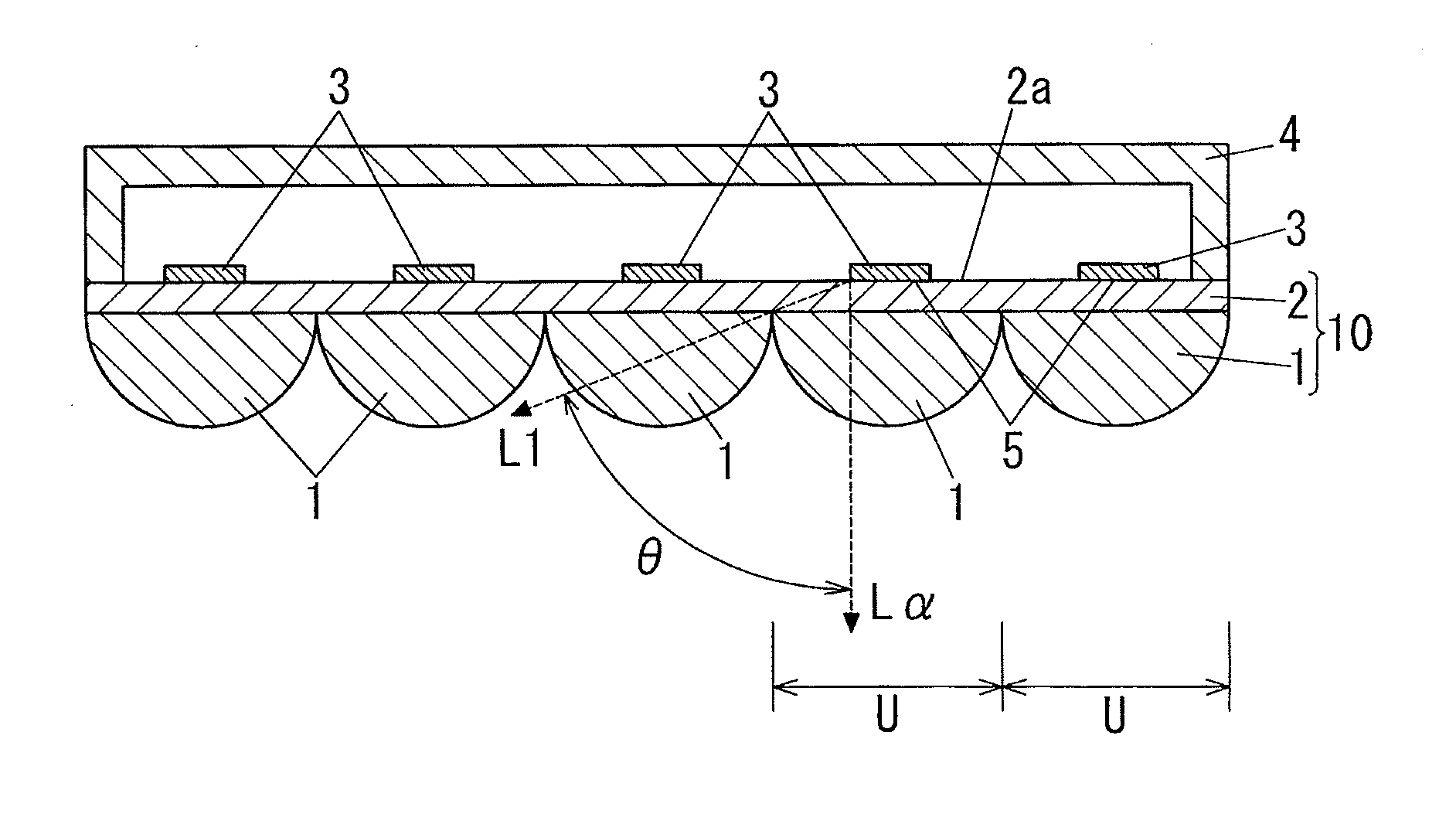
[0008]In an embodiment, the organic electroluminescence element 3 is configured to emit light in both a direction toward the substrate 2 and a direction opposite to the substrate 2, and the organic electroluminescence element 3 is provided on the side opposite to the substrate 2 with a lens structure section 6. In this invention, the organic electroluminescence element functions as a double-sided light emitting element, and then is sandwiched between lens structures, and thereby the lens structures are located in both light emission surface sides. Therefore, the emitted light can be extracted efficiently, and an efficient organic luminescent element can be provided.
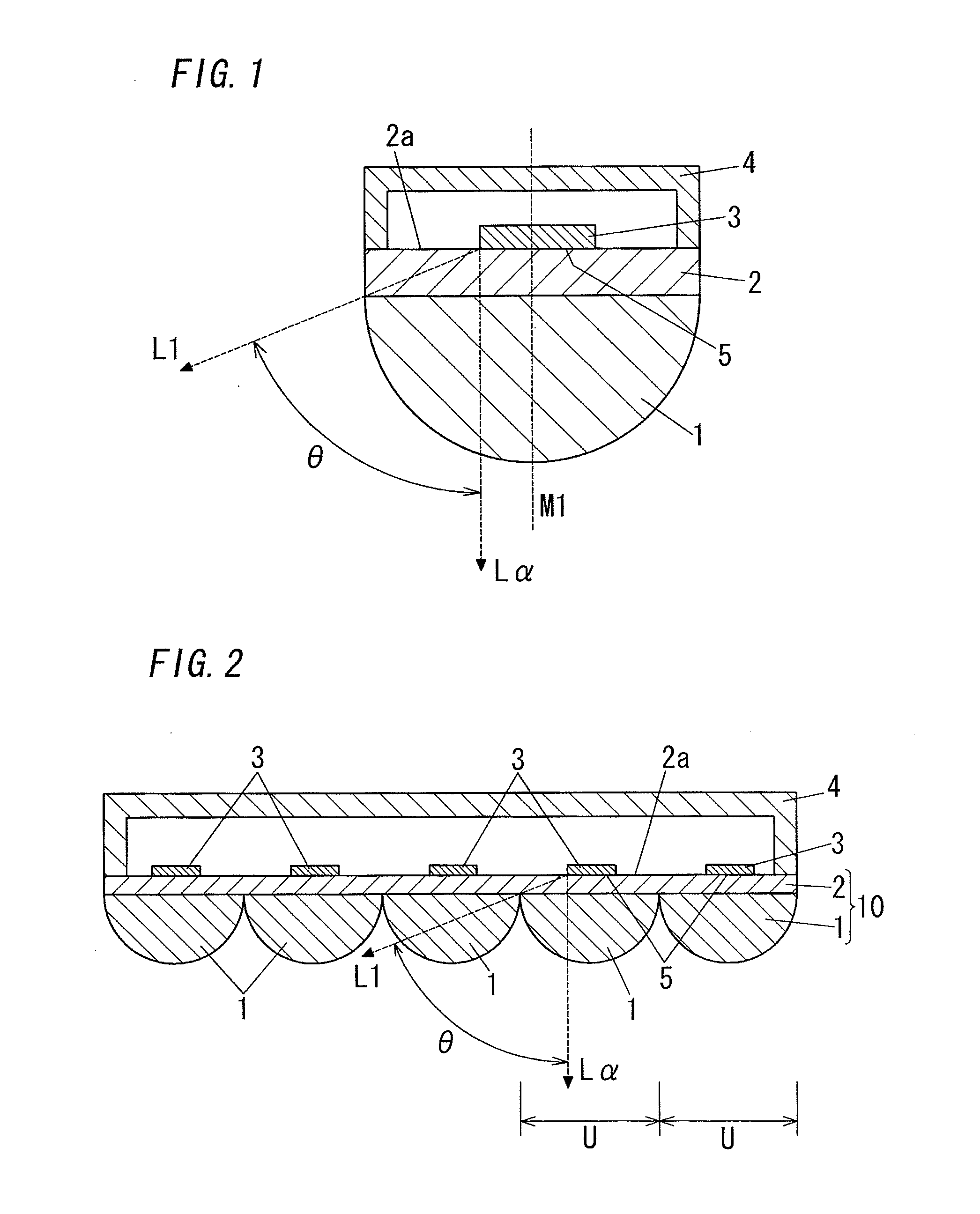
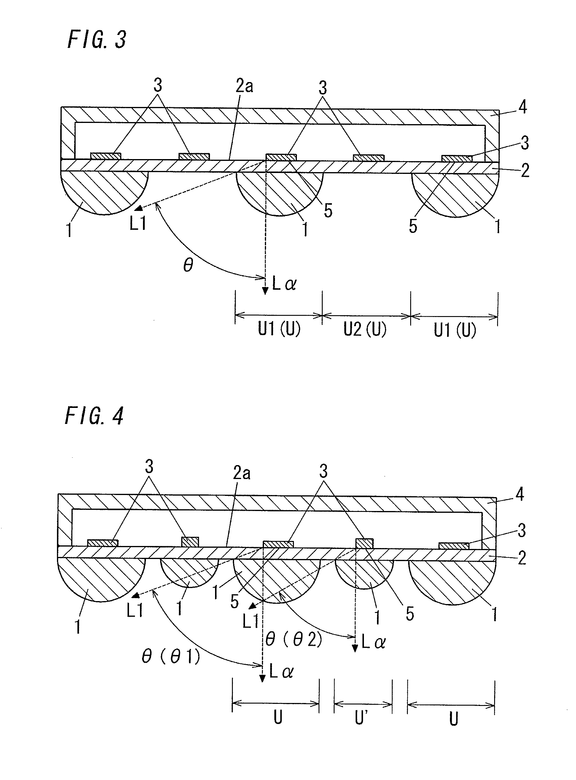
[0011]In an embodiment, the light-emitting section 5 has a laminate structure and comprises a first contact surface contacting with the substrate's surface, and said first contact surface is parallel to the substrate's surface. The lens 1 comprises a second contact surface contacting with the substrate 2, and said second contact surface is parallel to the substrate 2. An area of said first contact surface is set to be smaller than that of said second contact surface. In this invention, the emitted light can be radiated efficiently toward the substrate 2 and the lens 1. Thus, an efficient organic luminescent element can be provided.
[0012]In an embodiment, said first and second contact surfaces are formed into similarity shapes each other. In this invention, these contact surfaces are formed into, for example, circular shapes, rectangular shapes or elliptical shapes each other, and thereby an efficient organic luminescent element can be provided, and further can be manufactured easily.
[0013]In an embodiment, an angle between a line La perpendicular to said first contact surface and a straight line L1, connecting left ends or right ends of said first and second contact surfaces, is more than or equal to 60°, in a cross-section formed by cutting the organic luminescent element in a vertical direction so as to pass through at least a part of said first contact surface. In this invention, most of light emitted from the organic electroluminescence element can be extracted outside the element. Thus, an efficient organic luminescent element can be provided.
[0014]In an embodiment, said first and second contact surfaces are formed into circular shapes, and the light-emitting section 5 is located so that an optical axis M1 coincides with a central axis of the lens 1. An angle between a line La perpendicular to said first contact surface and a straight line L1, connecting left ends or right ends of said first and second contact surfaces, is more than or equal to 60°, in a cross-section formed by cutting the organic luminescent element in a vertical direction along the optical axis M1. In this invention, most of light emitted from the organic electroluminescence element can be extracted outside the element more efficiently. Thus, an efficient organic luminescent element can be provided.

Problems solved by technology

However, if the organic electroluminescence element is used as illumination purpose, the efficiency is still insufficient.
Thus, making higher efficient is required and becomes an issue.
However, total reflection at an interface between air and the substrate can not be prevented only by forming the substrate into the convex shape.
Therefore, the above organic electroluminescence element can not obtain sufficient luminance efficiency as illumination purpose.
In this method, although light emitted in a center part of the microlens can be extracted efficiently, light emitted in the remaining part of the microlens can not be extracted due to total reflection at an interface between air and a surface of the microlens.
As a result, making higher efficient has become an issue.

Method used


Image

  • Organic luminescent element
  • Organic luminescent element
  • Organic luminescent element

Examples


example 1

Practical Example 1

[0048]At first, ITO (Indium Tin Oxide, a sheet resistance of 12 [Ω / □]) having a thickness of 1100 [Å] was formed on one side of a glass substrate (a refractive index of 1.51) having a thickness of 0.5 [mm], and thereby a glass substrate with ITO was provided. The glass substrate with ITO was processed by ultrasonic cleaning with deionized water during ten minutes, and then by ultrasonic cleaning with acetone during ten minutes, and then by ultrasonic cleaning with isopropyl alcohol during ten minutes. After that, the glass substrate with ITO was processed by steam cleaning with isopropyl alcoholic vapor during two minutes, and then was dried, and further was processed by ultraviolet ozone washing during ten minutes.

[0049]Then, the glass substrate with ITO was put in a vacuum evaporation system, and a co-deposition film of molybdenum oxide (MoO3) and α-NPD was deposited as a hole injection layer under reduce pressure of 5*10−5 [Pa], and the co-deposition film had a...

example 2

Practical Example 2

[0051]A light-emitting section was formed into a circular shape having a radius of 0.5 [mm] (its area was about 0.785 [mm2]). In regard to the rest, an organic luminescent element was produced like the Practical Example 1. That is, an organic electroluminescence element was formed on a surface of a glass substrate so as to have the same layer configuration, and then a hemispherical lens (a refractive index of 1.51) having a diameter of 5 [mm] was adhered by using a liquid adhesion bond having a refractive index of 1.51 on the glass substrate, and the hemispherical lens was adjusted so that the center of its circle coincides with the center of the light-emitting section's circle, and thereby an organic luminescent element was produced.

example 3

Practical Example 3

[0052]ITO (a sheet resistance of 12 [Ω / □]) having a thickness of 1100 [Å] was formed on one side of a glass substrate (a refractive index of 1.75) having a thickness of 0.5 [mm] and thereby a glass substrate with ITO was provided. Then, an organic electroluminescence element was produced like the layer configuration of the Practical Example 1 (a light-emitting section: a circular shape having a radius of 1.5 [mm] and an area of about 7.07 [mm2]).

[0053]A hemispherical lens (a refractive index of 1.75) having a diameter of 5 [mm] was adhered by using a liquid adhesion bond having a refractive index of 1.75 on a surface of the side opposite to a surface of the glass substrate where the organic electroluminescence element was produced. An attachment area of the hemispherical lens was about 19.6 [mm2]. When the hemispherical lens was adhered on the glass substrate, the hemispherical lens was adjusted so that the center of its circle coincides with the center of the lig...


PUM


Abstract

An organic luminescent element comprises a substrate, an organic electroluminescence element formed on one surface thereof and having a light-emitting section emitting light to the substrate, and a lens attached on the other surface of the substrate. A refraction index of the lens is ≧ that of the substrate. An area of the light-emitting section, parallel to the substrate's surface, is smaller than an area of the substrate on which the lens is attached. An angle θ between a line perpendicular to the substrate's surface in a direction from the light-emitting section toward the substrate and a straight line connecting an end of the light-emitting section and an end of the lens, is set to be ≧60°.

Description

TECHNICAL FIELD[0001]The invention relates generally to organic luminescent elements and, more particularly, to an organic luminescent element using an organic electroluminescence element.BACKGROUND ART[0002]In recent years, an organic electroluminescence element, especially emitting white light, has become more efficient, and thus has been highly expected as a light source for the next generation which can replace a fluorescent being an existing major illumination lamp, or as a new illumination lamp for the next generation which could not be embodied by an existing light source.[0003]However, if the organic electroluminescence element is used as illumination purpose, the efficiency is still insufficient. Thus, making higher efficient is required and becomes an issue.[0004]In order to solve such an issue, there has been a development for efficiently extracting light emitted from the organic electroluminescence element. For example, an organic electroluminescence element having a tra...

Claims


Application Information

Patent Timeline
IPC IPC(8): H01J5/16
CPCH01L51/5275H10K50/858Y10S428/917
Inventor TSUJI, HIROYAITO, NORIHIROMATSUHISA, YUKOIDE, NOBUHIRO
Owner PANASONIC CORP
Learn More