
Wind turbine blade and its producing method

a technology of wind turbine blades and producing methods, which is applied in the direction of wind turbines with perpendicular air flow, wind turbines with parallel air flow, wind turbines, etc., to achieve the effect of saving labor costs

Active Publication Date: 2012-09-20
GURIT TOOLING (TAICANG) CO LTD
View PDF23 Cites 20 Cited by
  • Summary
  • Abstract
  • Description
  • Claims
  • Application Information

AI Technical Summary

Benefits of technology

[0006]The present invention aims to combine the low cost of method 1 with the high quality of method 3, and overcome the difficulty of joining the dissimilar materials using novel adhesives.
[0016]1. An optimal distribution of high strength resin matrix in critical areas, low cost resin matrix in non-critical areas, and the two being joined by use of third resin type as an adhesive.
[0018]3. Potential savings of labor cost during production by using polyester gelcoats instead of painting.

Problems solved by technology

1. Production of the blade by resin infusion using polyester or vinyl ester resin. In such blades, the shell and the cap layers of the structural box caps are made in a single infusion process, then joined with shear webs (see illustrations section). The aerodynamic shell and the structural box caps are not independent parts, and the whole body is infused with the same resin. Such structure has the disadvantage that the inferior fatigue and strength properties of the lower cost resins mean that more volume of laminate must be used, resulting in a heavier blade. Further, such structure has the disadvantage of possessing areas of critical structural bonding, placing a high requirement on the strength of the bonding adhesive and good preparation of the surfaces to be joined, by grinding or other roughening techniques. Such structure requires well trained and monitored workers to prevent the development of quality defects during the production process. The process is prone to occurrence of air inclusions in the resin, wrinkles in the dry fiberglass, oversized or poorly matched structural bond lines, and failed structural bonding do to surface contamination or insufficient surface roughening. These common faults have been sources of numerous blade failures in service over the past 2 decades.
2. Production of the blade by resin infusion or hand lamination, using epoxy resin. In such process, the cap layers of the structural box are produced in a first ‘prefab’ step, then the ‘prefab’ is laid into the structural shell, which subsequently completely envelopes the ‘prefab’ parts. The aerodynamic shell and the structural box are not independent parts. Such structure has disadvantage of using more expensive epoxy resin throughout, while achieving only mid-level fatigue and strength properties. Further, such structure shares all the disadvantages of method 1, regarding the structural bonding and quality control problems. The only real difference from method 1 is a use of a more expensive resin matrix to generate some weight savings.
3. Production of the structural box in a single piece by laying epoxy-fiberglass and / or epoxy-carbon fiber prepreg layers onto a box shaped male mandrel. A separate non structural shell from similar type epoxy based prepreg material is formed in two haves using other moulds. Then the shells and the structural box are bonded together. However, as the shell is not a load carrying member, but merely an aerodynamic fairing, the joint is not a load carrying structural bond. The standards for joint preparation and adhesive strength can therefore be relaxed considerably. This production technique eliminates much of the quality control risk associated with methods 1 & 2. Air inclusions and wrinkles can be eliminated altogether, while the issue of bonding quality becomes much less important. However, this approach results in considerably higher cost, since costly multi-axial prepreg is also used for the non-structural shell, where superior structural properties provide little benefit. Further, because the prepreg shell material requires a higher curing temperature, more expensive high temperature resistant SAN (styro acryl nitrile), PVC (poly vinyl chloride) or PET (polyethylene terephthalate) foam core must be used within the blade shell sandwich laminate, in place of the balsa wood or low cost foam preferred for methods 1 & 2. Also, the shell moulds need to be capable of higher temperatures in order to cure the prepreg material, adding additional cost.

Method used


Image

  • Wind turbine blade and its producing method
  • Wind turbine blade and its producing method
  • Wind turbine blade and its producing method

Examples


Embodiment Construction

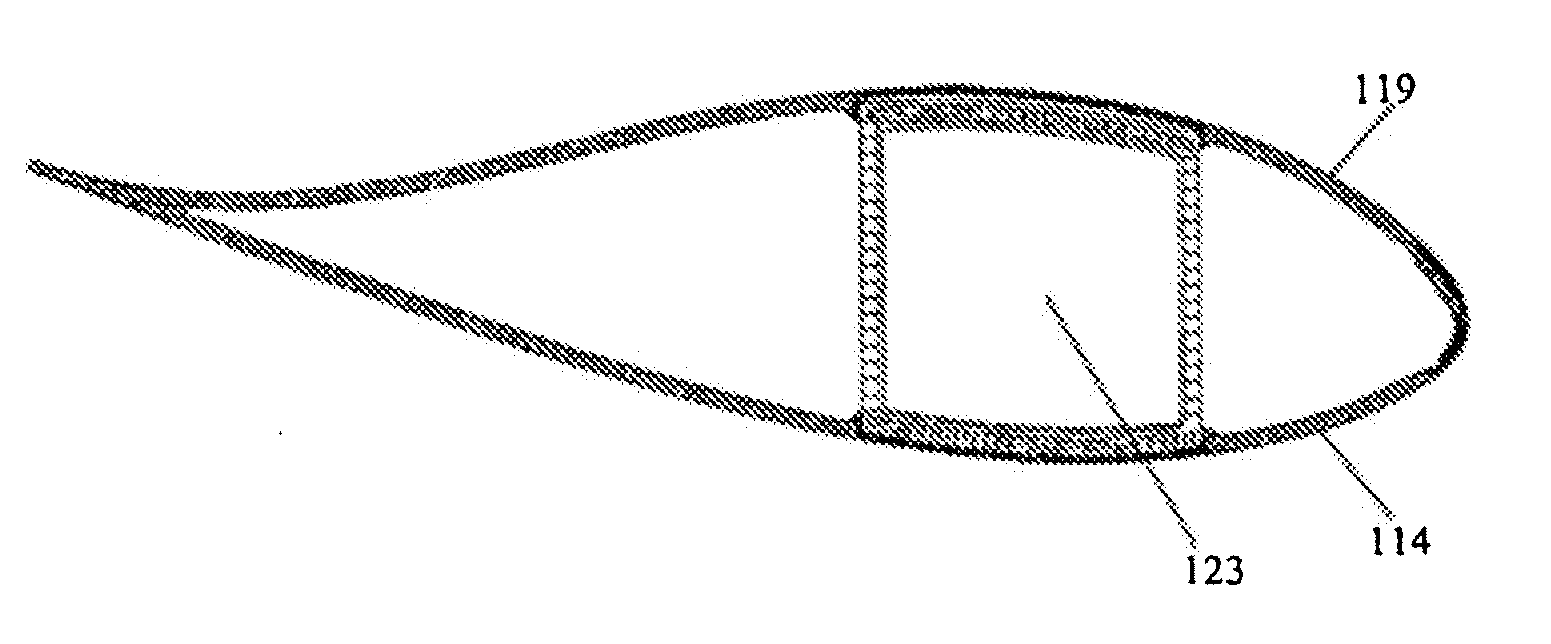
[0033]Generally, a wind turbine blade comprises a structural box and a shell consisting of an upper shell part and a lower shell part. The structural box is a load carrying member, and the shell is not a load carrying member, but merely an aerodynamic fairing. According to the present invention, the structural box and the shell are independent parts that are made by using separate moulds.

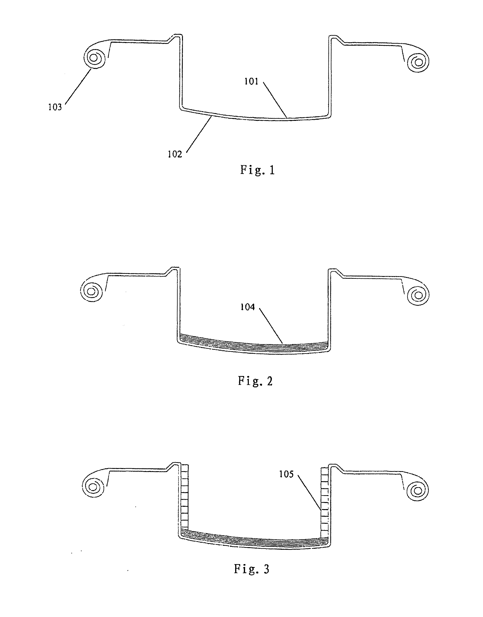
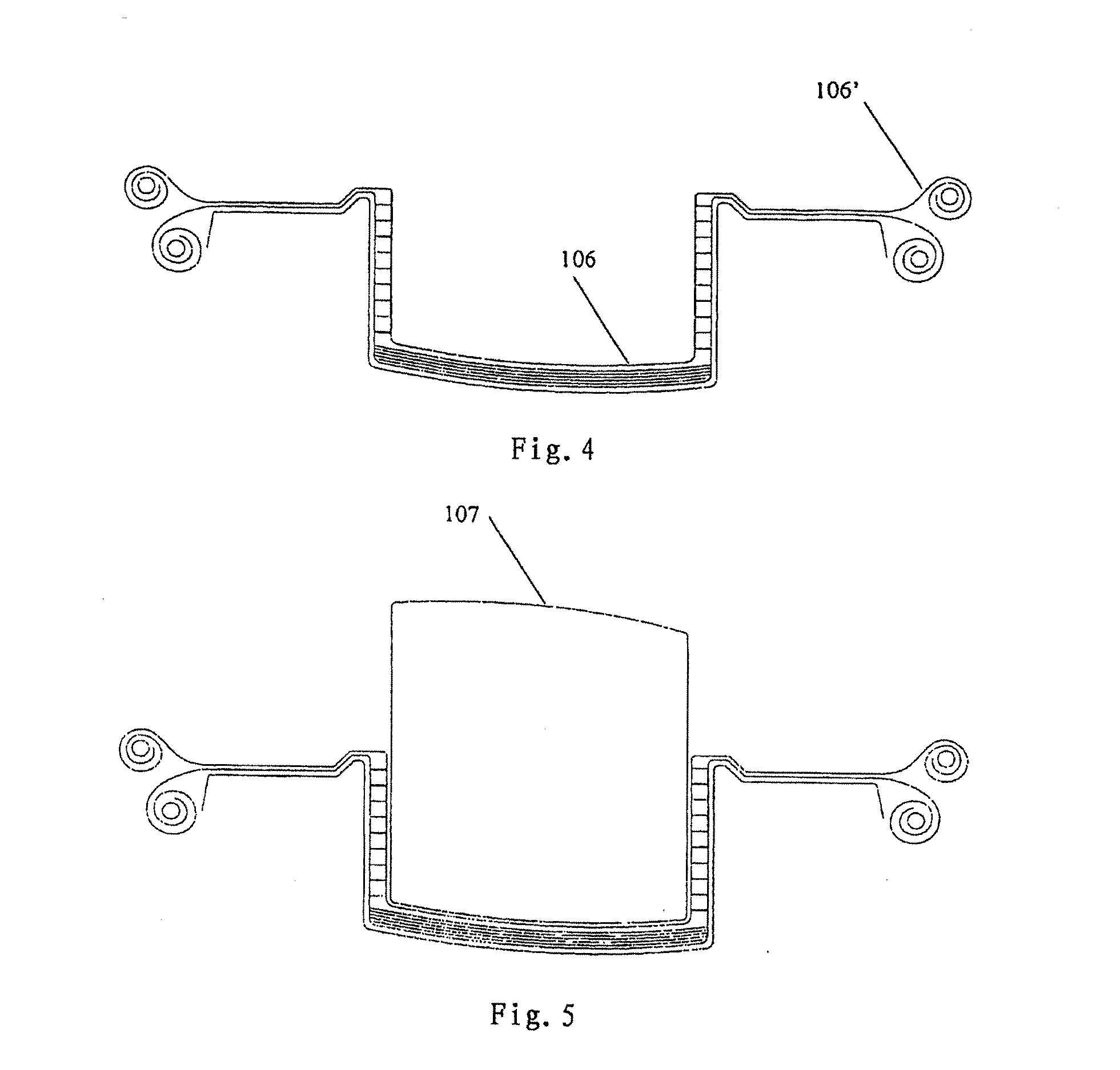
[0034]Now, a description will be first given to the production of the structural box with reference to FIGS. 1-10.

[0035]A lower structural box mould 102 is provided for forming a lower half of the structural box. Outer cover layers 101 of the lower half of the structural box, made up of multiaxial prepreg material, are laid into the lower structural box mould 102. Excess material 103 is left rolled up on both sides of the mould cavity.

[0036]Then, cap layers 104 of the lower half of the structural box, made up of unidirectional prepreg, are stacked into the bottom of the lower structural box mould.

[0...


PUM

PropertyMeasurementUnit
thicknessaaaaaaaaaa
densityaaaaaaaaaa
densityaaaaaaaaaa

Abstract

The present invention provides a wind turbine blade of hybrid material composition, wherein the blade comprises a structural box mainly made of a epoxy based prepreg and a shell manufactured by resin infusion technique using polyester or vinylester, and the box and the shell are bonded using an adhesive that is not a polyester, a vinylester and an epoxy. The present invention also provides a method for producing such a blade.

Description

TECHNICAL FIELD[0001]The present invention relates to a wind turbine blade and a method for producing such a blade.BACKGROUND TO THE CURRENT INVENTION[0002]The wind power industry has long seen three main approaches to the structural design and production of wind turbine blades:[0003]1. Production of the blade by resin infusion using polyester or vinyl ester resin. In such blades, the shell and the cap layers of the structural box caps are made in a single infusion process, then joined with shear webs (see illustrations section). The aerodynamic shell and the structural box caps are not independent parts, and the whole body is infused with the same resin. Such structure has the disadvantage that the inferior fatigue and strength properties of the lower cost resins mean that more volume of laminate must be used, resulting in a heavier blade. Further, such structure has the disadvantage of possessing areas of critical structural bonding, placing a high requirement on the strength of t...

Claims


Application Information

Patent Timeline
Patent Type & Authority Applications(United States)
IPC IPC(8): B32B37/14F03D1/06B32B37/12
CPCB29C66/1312Y10T156/10B29C66/54B29C66/61B29C66/71B29C66/721B29C66/7212B29C70/342B29D99/0028B29L2031/085F03D3/062F05B2280/6003F05C2253/04Y02E10/721Y02E10/74B29C66/532B29C65/483B29C66/712B29K2307/04B29K2309/08B29K2063/00B29K2067/00B29K2031/00Y02E10/72Y02P70/50F03D1/0675
Inventor MIRONOV, GABRIEL
Owner GURIT TOOLING (TAICANG) CO LTD
Learn More