Magnetic recording device and magnetic recording method

a recording device and magnetic recording technology, applied in the field of magnetic recording devices and magnetic recording methods, can solve the problems of reducing the surface recording density of the magnetic recording medium, physical difficulty in performing data rewriting processing in only an arbitrary unit recording region, etc., and achieve the effect of reducing the width of the erase band eb, improving the surface recording density of the magnetic disk 201, and improving the format efficiency

Active Publication Date: 2012-09-20
TDK CORPARATION
View PDF4 Cites 9 Cited by
  • Summary
  • Abstract
  • Description
  • Claims
  • Application Information

AI Technical Summary

Benefits of technology

[0084]In the magnetic disk device of the embodiment, when data is recorded on the magnetic disk 2, the magnetic read write head 212 is allowed to travel only in a direction from an outer write track toward an inner write track, across write tracks in the magnetic disk 201. Therefore, compared with the case where the magnetic read write head 212 is allowed to travel bi-directionally, format efficiency may be improved. Moreover, in the magnetic read write head 212, the distance between the front end portion 14A of the main magnetic-pole layer 14, the side shields 16A and 16B, and the leading shield 8B is maintained uniform with the gap layer therebetween. Therefore, the width of the erase band EB may be minimized, and surface recording density of the magnetic disk 201 may be improved without reducing an effective write track width.

Problems solved by technology

However, due to such characteristics, except for a final write track, performing data rewriting processing in only an arbitrary unit recording region is physically difficult.
However, when the track pitch is widened, error such as miswriting is avoidable, but the reduction of the surface recording density of the magnetic recording medium inevitably arises.

Method used


Image

  • Magnetic recording device and magnetic recording method
  • Magnetic recording device and magnetic recording method
  • Magnetic recording device and magnetic recording method

Examples


Embodiment Construction

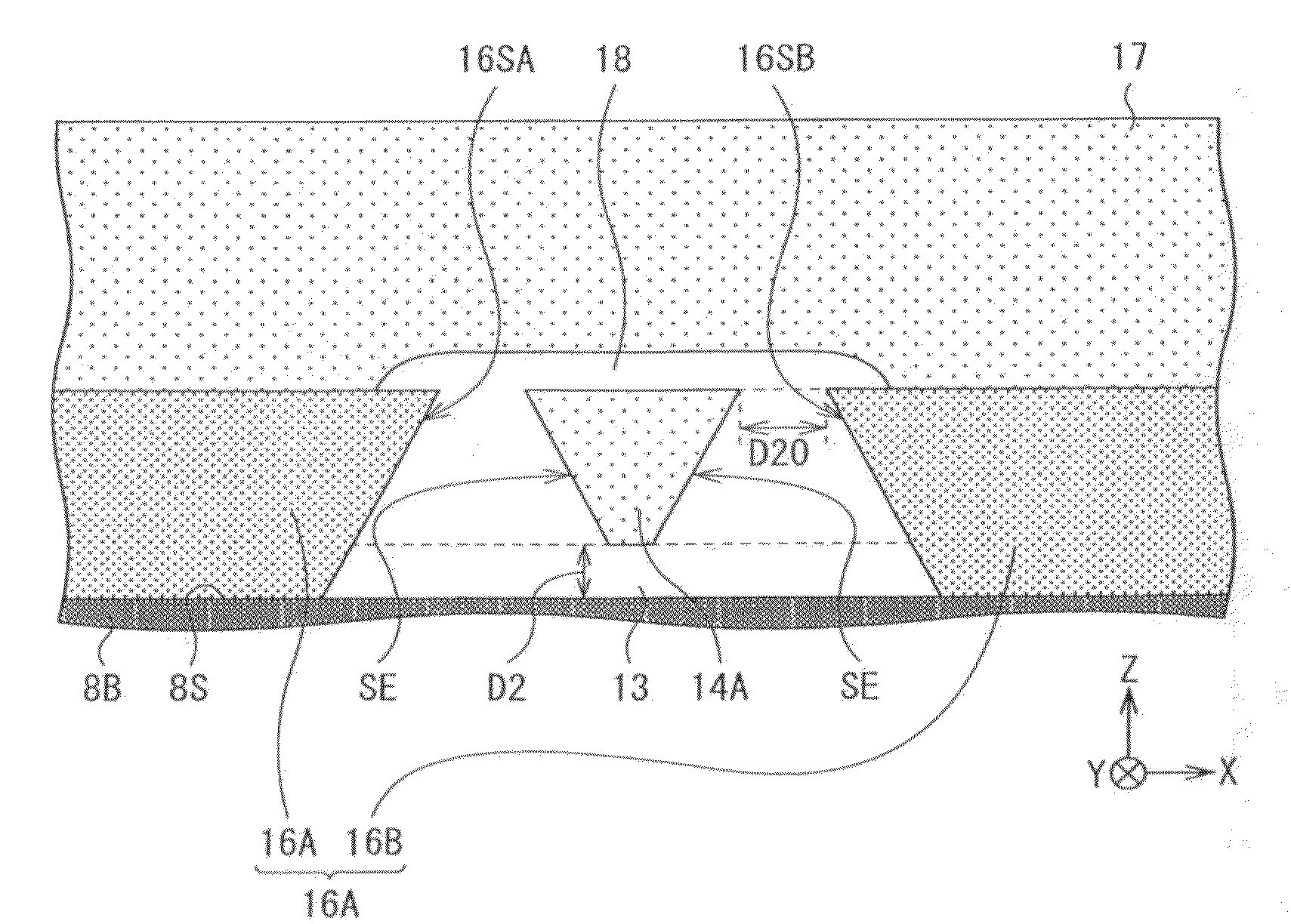
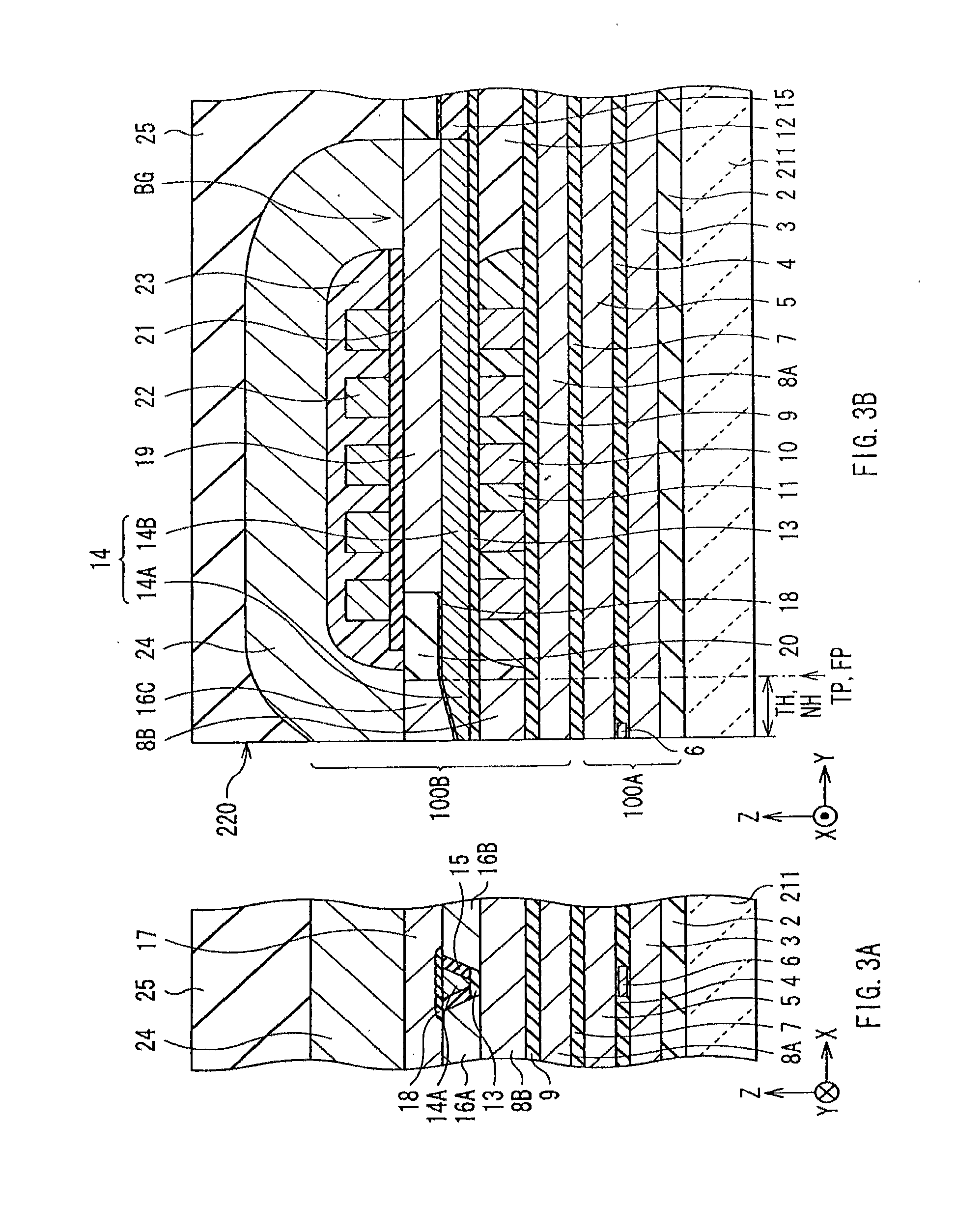
[0032]Hereinafter, a preferred embodiment of the invention will be described in detail with reference to drawings.

[Configuration of Magnetic Disk Device]

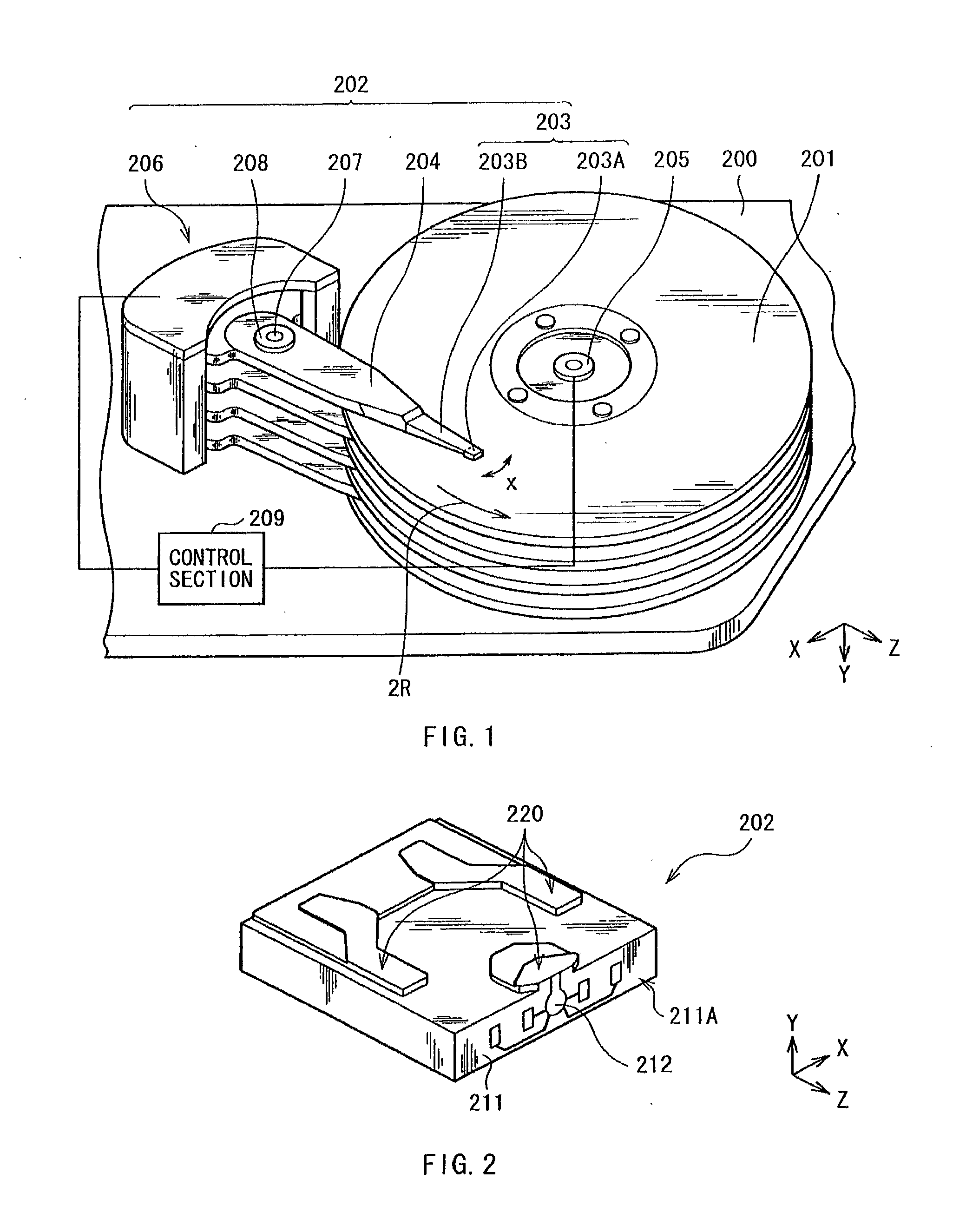
[0033]First, referring to FIG. 1 and FIG. 2, a configuration of a magnetic disk device mounted with a magnetic read write head will be described.

[0034]FIG. 1 is a perspective view illustrating an internal configuration of a magnetic disk device as the embodiment. The magnetic disk device is a hard disk drive employing a shingle write method as a recording method and a load / unload method as a driving method. The magnetic disk device includes, for example, in a housing 200, a magnetic disk 201 as a magnetic recording medium in which information is to be recorded, and a head arm assembly (HAA) 202 for recording information on the magnetic disk 201 and reproducing the information. The HAA 202 is provided with a head gimbals assembly (HGA) 203, an arm 204 supporting a base of the HGA 203, and a driving section 206 as a power source for r...


PUM

PropertyMeasurementUnit
width W1aaaaaaaaaa
thickness D2aaaaaaaaaa
thicknessaaaaaaaaaa

Abstract

A magnetic disk device includes: a recording medium provided with a plurality of write tracks; a magnetic write head including a magnetic pole, side shields, and a leading shield, a distance from the magnetic pole to each of the side shields being maintained to be uniform with a gap layer therebetween, and a distance from the magnetic pole to the leading shield being maintained to be uniform with a gap layer therebetween; and a control section rotating the recording medium, and allowing magnetic information to be recorded on the recording medium while allowing the magnetic write head to travel in a direction from an inner write track toward an outer write track or in a direction from the outer write track toward the inner write track, across write tracks in the recording medium. With such a configuration, format efficiency may be improved, and a width of an erase band on a magnetic disk may be minimized. Therefore, surface recording density of a recording medium may be improved without reducing an effective write track width.

Description

BACKGROUND OF THE INVENTION[0001]1. Field of the Invention[0002]The present invention relates to a magnetic recording device and a magnetic recording method.[0003]2. Description of Related Art[0004]Recently, with increasing surface recording density of a magnetic recording medium (hereinafter, referred to as a “recording medium”) typified by a hard disk, performance improvement of a magnetic write head is demanded. Accordingly, as a recording method with the magnetic write head, a vertical magnetic recording method in which a direction of signal magnetic field is set in a direction intersecting with a plane of a magnetic recording medium is attracted attention, instead of a longitudinal magnetic recording method in which a direction of signal magnetic field is set in an in-plane direction of a recording medium. This is because in the vertical magnetic recording method, linear recording density is increased, and an advantage that a recorded recording medium is hardly affected from th...

Claims


Application Information

Patent Timeline
Patent Type & Authority Applications(United States)
IPC IPC(8): G11B21/02G11B21/04
CPCG11B5/012G11B5/315G11B5/3116G11B5/1278
Inventor HIRATA, KEIKIYONO, HIROSHINAKADA, OSAMUANAGAWA, KENKICHI
Owner TDK CORPARATION
Why Eureka
Try Eureka