
Apparatus and method for ion mobility spectrometry and sample introduction

a technology of ion mobility spectrometry and apparatus, applied in the field of apparatus and method for ion mobility spectrometry and sample introduction, can solve the problems of reducing length, compromising detection limits, and dead volume due to transfer lines cannot be completely eliminated, so as to reduce or eliminate cross contamination, reduce or eliminate liquid dead volume, and maximize sample throughput

Inactive Publication Date: 2012-09-13
EXCELLIMS CORP
View PDF37 Cites 17 Cited by
  • Summary
  • Abstract
  • Description
  • Claims
  • Application Information

AI Technical Summary

Benefits of technology

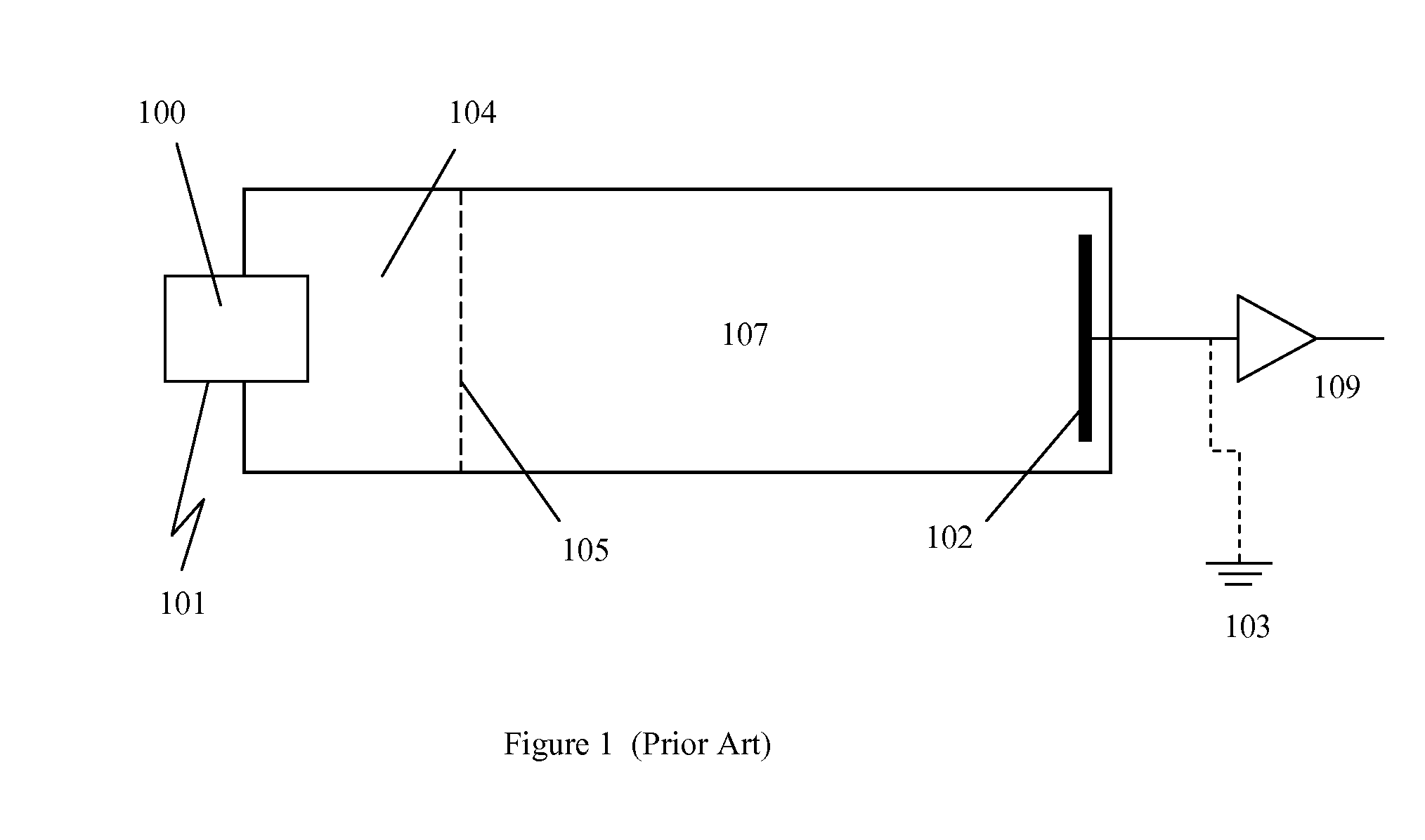
[0003]The IMS apparatus and methods described in this invention involve setting the ion detector at the highest potential of the drift tube and setting the ionization source at ground or near ground potential. The methods allow significantly simple sample introduction without the limitation of the high potential (voltage) concern of the front end sample delivery. The invention also describes bringing samples directly into the ion mobility drift tube. The invention further describes using single syringe for sample introduction via an electrospray ionization method.
[0005]The invention comprises a reusable or disposable needle configured in an auto-injector or a manual injector which serves as the means to remove a sample solution from a container and transport such solution to an atmospheric pressure ionization (API) source (such as ESI or APCI) wherein the needle is to deliver sample directly into the API source and / or desolvation region. Such fixed or disposable needle, when introduced into an API source, becomes the liquid introduction channel or tube in the nebulizer probe of an APCI source, the nebulizer apparatus of a pneumatically assisted Electrospray probe or an Electrospray tip in an unassisted ESI ion source probe. Ions produced from samples introduced through such sprayers into an API source are subsequently directed into a desolvation region of the IMS. Auto injectors may be configured with multiple injector needles configured for direct delivery of sample into an API source through one or more probes. Such multiple needle auto injectors may deliver samples in a sequential or multiplexed manner to such single or multiple direct injection API source ports or probes to maximize sample throughput. In one embodiment of the invention, a reusable or disposable sampling and spray injection needle may be packed with material, such as C18 coated beads, to aid in desalting, sample cleanup or the separation of sample compounds in solution during the sample pickup, delivery and spray steps. Different solvent composition layers can be pulled sequentially into such packed sampling and spray needles with attached reservoirs prior to sample pickup. The sample can then be sprayed into an API source from such a loaded injection needle using solvent gradients to aid in sample desalting, additional cleanup or sample compound separation during spraying.
[0007]The invention eliminates the need for sample injector valves or transfer lines into an API source, reducing sample dilution, loss and contamination due to sample handing and transfer. When a reusable needle is configured in the invention, the needle inner bore and outer surface can be washed in between each sample delivery and spraying step to reduce or eliminate, chemical noise, cross talk or carry over from one sample to the next. The use of disposable needles, configured according to the invention, eliminates sample to sample cross talk or contamination without a wash step between sample injections into the API source. Faster cycle times or more rapid sample injection throughput can be achieved by eliminating wash steps. Alternatively, a wash step can be run for one or more reusable injection needles while sample delivery and spraying is occurring with another injection needle or needles. The invention reduces apparatus costs, sample losses, sample contamination, and sample handling and minimizes solvent consumption and waste while increasing sample throughput in flow injection analysis with Atmospheric pressure ion sources. A direct injection needle apparatus may be configured with other API inlets in the same API source chamber as a means to increase analytical flexibility within one API source apparatus. Ions produced from the API source may be analyzed by an apparatus other than MS including but not limited to ion mobility analyzers.

Problems solved by technology

Liquid transfer lines can be reduced in length when an ESI source in configured with a grounded needle, however, even with grounded ESI needles, the dead volume due to the transfer lines cannot be entirely eliminated.
For ion mobility spectrometer (IMS) applications where small amounts of sample are available for injection, sample dilution or losses due to injector valve, connector and transfer line dead volumes and surfaces may compromise the limit of detection.

Method used


Image

  • Apparatus and method for ion mobility spectrometry and sample introduction
  • Apparatus and method for ion mobility spectrometry and sample introduction
  • Apparatus and method for ion mobility spectrometry and sample introduction

Examples


Embodiment Construction

[0014]Unless otherwise specified in this document the term “ion mobility based spectrometer” is intended to mean any device that separates ions based on their ion mobilities and / or mobility differences under the same or different physical and / or chemical conditions, the spectrometer may also include detecting the ions after the separation process. Many embodiments herein use the time of flight type IMS as examples; the term ion mobility based spectrometer shall also include many other kinds of spectrometers, such as differential mobility spectrometer (DMS) and field asymmetric ion mobility spectrometer (FAIMS). Unless otherwise specified, the term ion mobility spectrometer or IMS is used interchangeable with the term ion mobility based spectrometer defined above.

[0015]As used herein, the term “analytical instrument” generally refers to ion mobility based spectrometer, MS, and any other instruments that have the same or similar functions. Unless otherwise specified in this document t...


PUM


Abstract

The IMS apparatus and methods described in this invention involve setting the ion detector at the highest potential of the drift tube and setting the ionization source at ground or near ground potential. The methods allow significantly simple sample introduction without the limitation of the high potential (voltage) concern of the front end sample delivery. The invention also describes bringing samples directly into the ion mobility drift tube. The invention further describes using single syringe for sample introduction via an electrospray ionization method.

Description

[0001]The present application claims the benefit of and priority to corresponding U.S. Provisional Patent Application No. 61 / 452,117, filed Mar. 13, 2011 respectively, the entire content of the application is herein incorporated by reference.BACKGROUND OF THE INVENTION[0002]The needle in some commercial electrospray ionization (ESI) sources is operated at kilovolt potentials during electrospray operation. For such ESI sources, a longer dielectric liquid transfer line of several inches is typically configured between the ground potential injector valve and the ESI needle to allow a gradual drop in kilovolt potential through the sample solution. A high electric field gradient in the transfer tube is avoided to minimize sample heating, electrophoretic and electrolysis effects during Flow injection analysis (FIA). Liquid transfer lines can be reduced in length when an ESI source in configured with a grounded needle, however, even with grounded ESI needles, the dead volume due to the tra...

Claims


Application Information

Patent Timeline
IPC IPC(8): H01J49/26
CPCG01N27/622H01J49/165H01J49/067G01N27/624H01J49/167
Inventor WU, CHINGOSGOOD, MARK A.HAINSWORTH, EUGENIEKRUEGER, CLINTON ALAWNKIM, TAEMAN
Owner EXCELLIMS CORP
Learn More