
Thermal transfer mechanisms for an auger pyrolysis reactor

a technology of pyrolysis reactor and transfer mechanism, which is applied in the direction of mechanical conveying coke oven, fuel, biofuel, etc., can solve the problems of low heat transfer rate, limited production capacity, and production of condensate that is not at thermodynamic equilibrium, and achieve the effect of adequate pyrolysis hea

Inactive Publication Date: 2012-09-13
MISSISSIPPI STATE UNIVERSITY
View PDF3 Cites 9 Cited by
  • Summary
  • Abstract
  • Description
  • Claims
  • Application Information

AI Technical Summary

Benefits of technology

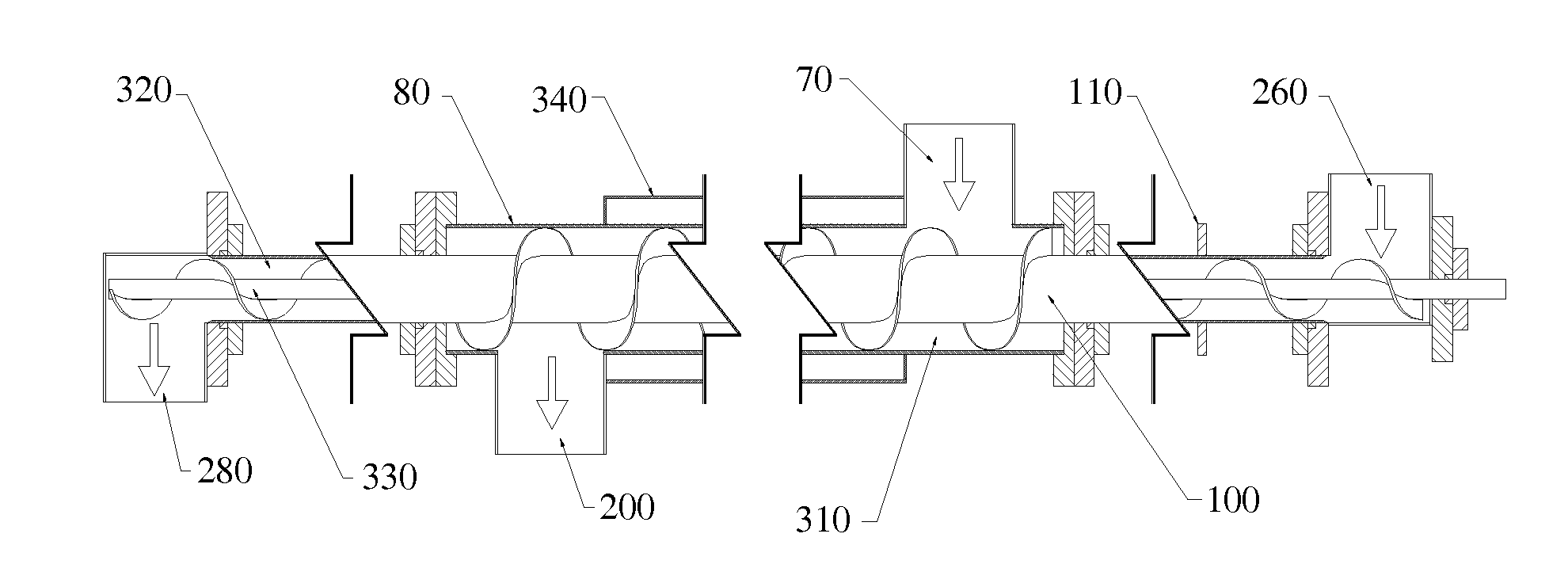
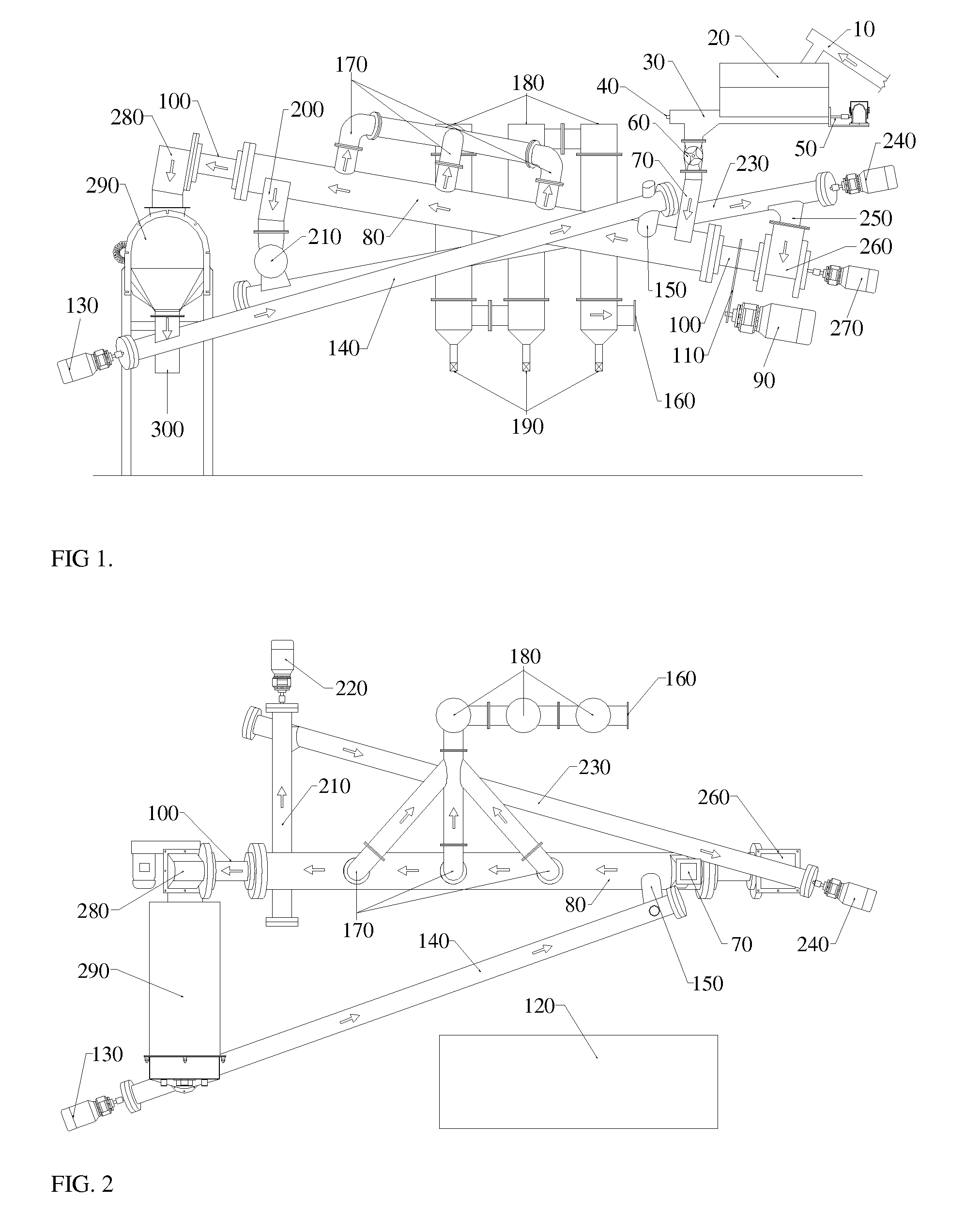
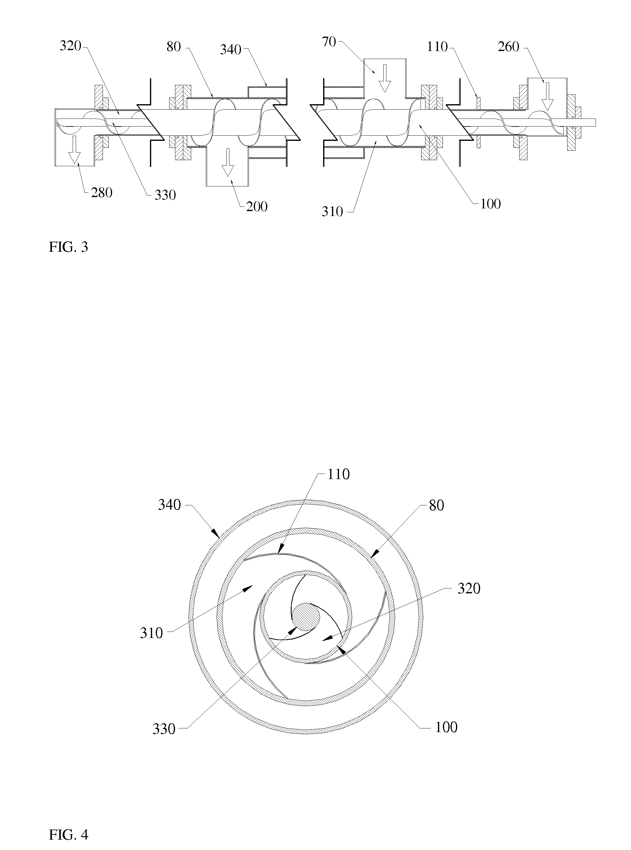
[0013]It is the object of the present invention to provide a source of pyrolysis heat carried by a SHC by using the hot SHC/char mixture produced during pyrolysis in the shell of an auger reactor for pyrolysis heat. Following the pyrolysis of the biomass feedstock in the main reactor tube, the mixture of hot SHC and char remains at high temperature. By our method, this hot SHC/char mixture is fed into the hollow shaft of the main auger reactor shaft to heat the auger shaft internally by conduction. This conducted heat is transferred from the internal surface of the internal auger tube to the external surface and is subsequently transferred, via both conduction and convection, to the SHC/feedstock mixture fed by the auger through the main reactor tube (MRT) shell. Auger reactor tubes f

Problems solved by technology

The rapidity of the thermal biomass decomposition results in the production of a condensate that is not at thermodynamic equilibrium at normal storage temperatures.
In practice, and particularly in scale up to industrial production, there are drawbacks to each of these designs that have precluded commercialization for all but Ensyn's entrained down-flow reactor.
However, production capacity is limited by the small tube diameter hampering scale up to industrial production.
Larger tube diameters result in low heat transfer rates that require slow augering of the biomass through the tube.
This results in slow pyrolysis with corresponding low liquid bio-oil yields.
Practitioners of the auger pyrolysis reactor design have attempted to solve the slow heating-rate issue in order to achieve fast pyrolysis by developing means to provide additional heat beyond that applied to the external surface of the auger tube in various ways, but none of them have been as successful as the method disclosed herein.

Method used


Image

  • Thermal transfer mechanisms for an auger pyrolysis reactor
  • Thermal transfer mechanisms for an auger pyrolysis reactor
  • Thermal transfer mechanisms for an auger pyrolysis reactor

Examples


Embodiment Construction

[0019]The following detailed description is presented to enable any person skilled in the art to make and use the invention. For purposes of explanation, specific details are set forth to provide a thorough understanding of the present invention. However, it will be apparent to one skilled in the art that these specific details are not required to practice the invention. Descriptions of specific applications are provided only as representative examples. Various modifications to the preferred embodiments will be readily apparent to one skilled in the art, and the general principles defined herein may be applied to other embodiments and applications without departing from the scope of the invention. The present invention is not intended to be limited to the embodiments shown, but is to be accorded the widest possible scope consistent with the principles and features disclosed herein.

[0020]The preferred embodiment of the current invention is to utilize the SHC to provide pyrolysis heat...


PUM


Abstract

An improved method of providing heat to a pyrolysis reactor is disclosed. A solid heat carrier produces fast pyrolysis vapors during transport of the solid heat carrier / feedstock mixture down the shell of the main reactor tube by the reactor tube auger. These vapors are drawn from the main reactor tube by a slight vacuum pressure and are condensed in a multiple condenser train comprised of shell and tube condensers cooled by water or other means.

Description

STATEMENT REGARDING FEDERALLY SPONSORED RESEARCH OR DEVELOPMENT[0001]This invention was made with Government support under DE-FG36-06GO86025 awarded by the U. S. Department of Energy. The Government has certain rights in the invention.CROSS-REFERENCES TO RELATED APPLICATIONS[0002]NoneFIELD OF THE INVENTION[0003]The present invention is generally directed toward a method of supplying heat for pyrolysis by a solid heat carrier.BACKGROUND OF THE INVENTION[0004]Fast pyrolysis produces a liquid product, known as pyrolysis oil or bio-oil. The required pyrolysis conditions for fast pyrolysis are a temperature of 400° C. to 650° C. and the absence of oxygen. This temperature range results in the decomposition of the biomass cell structures into their molecular components. At these moderate temperatures, a fraction of biomass is converted to approximately 10% to 15% syngas by pyrolysis, but the majority is converted to pyrolysis oil (60% to 70%) or char (15%). Bio-oil chemical properties var...

Claims


Application Information

Patent Timeline
IPC IPC(8): C10B51/00
CPCC10B7/10C10B47/44C10B51/00C10B53/02Y02E50/15C10C5/00C10L9/083Y02E50/14C10B57/06Y02P30/20Y02E50/10
Inventor STEELE, PHILIP H.MITCHELL, BRIAN
Owner MISSISSIPPI STATE UNIVERSITY
Learn More