
Cooling system of an internal combustion engine having charge air feed

a technology of charge air feed and cooling system, which is applied in the direction of machines/engines, mechanical equipment, non-fuel substance addition to fuel, etc., can solve the problems of lower engine performance and achieve the effect of simple control technology design

Active Publication Date: 2011-01-25
MAN TRUCK & BUS AG
View PDF22 Cites 20 Cited by
  • Summary
  • Abstract
  • Description
  • Claims
  • Application Information

AI Technical Summary

Benefits of technology

This solution allows for reliable prevention of unnecessary cooling in specific operating states, shortening hot running phases and enabling immediate responses to changes in engine parameters, thereby optimizing engine performance and reducing nitrogen oxide emissions.

Problems solved by technology

This reduction of the oxygen proportion causes a lower performance increase of the engine.
The previously described systems have the disadvantage that, in each case the cooling loop operated at a lower temperature level and into which the intercoolers are also coupled, for example, is supplied with coolant in all operating states, so that the corresponding engine components are cooled at all times during operation of the internal combustion engine.

Method used


Image

  • Cooling system of an internal combustion engine having charge air feed
  • Cooling system of an internal combustion engine having charge air feed
  • Cooling system of an internal combustion engine having charge air feed

Examples


Embodiment Construction

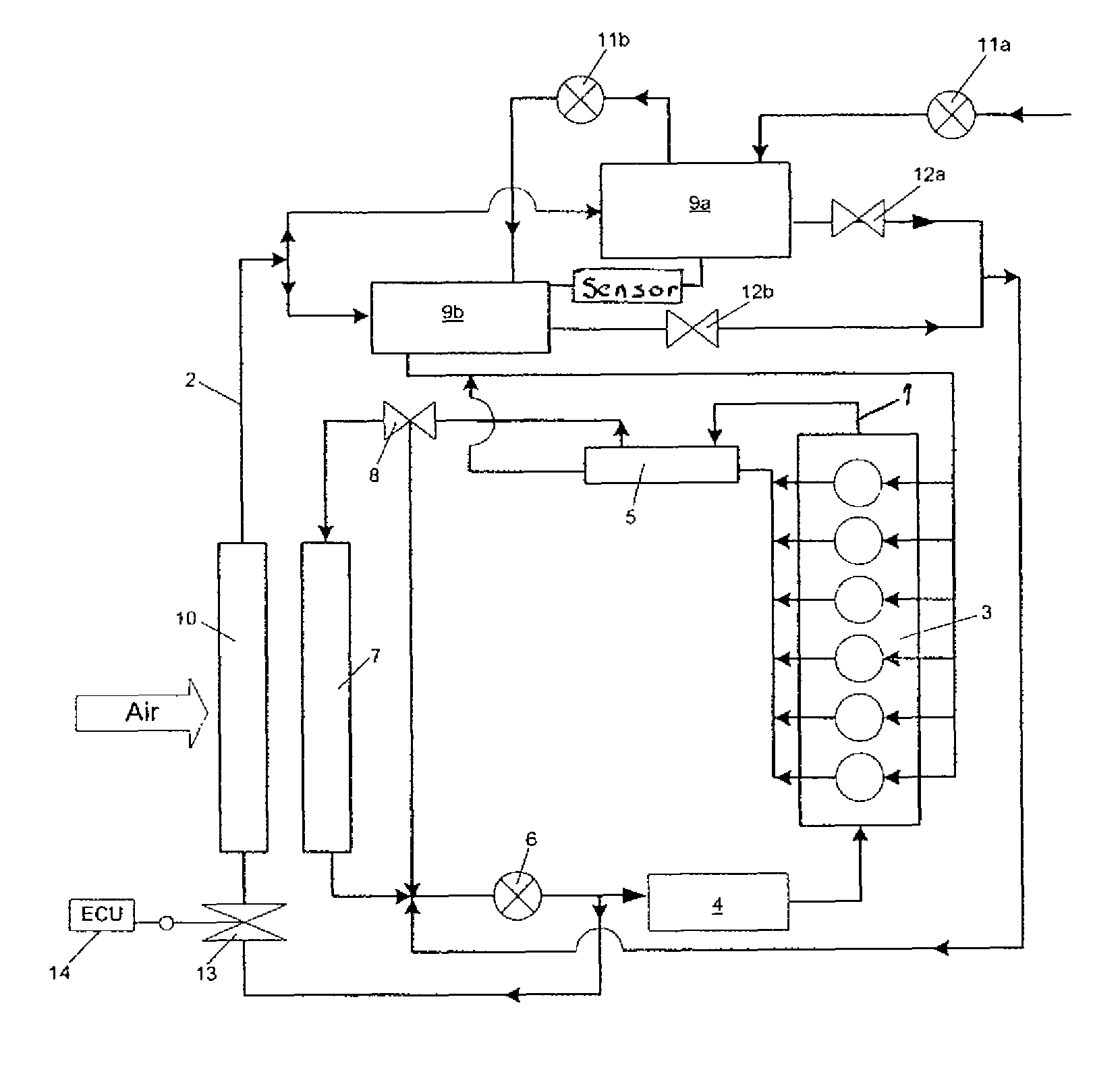
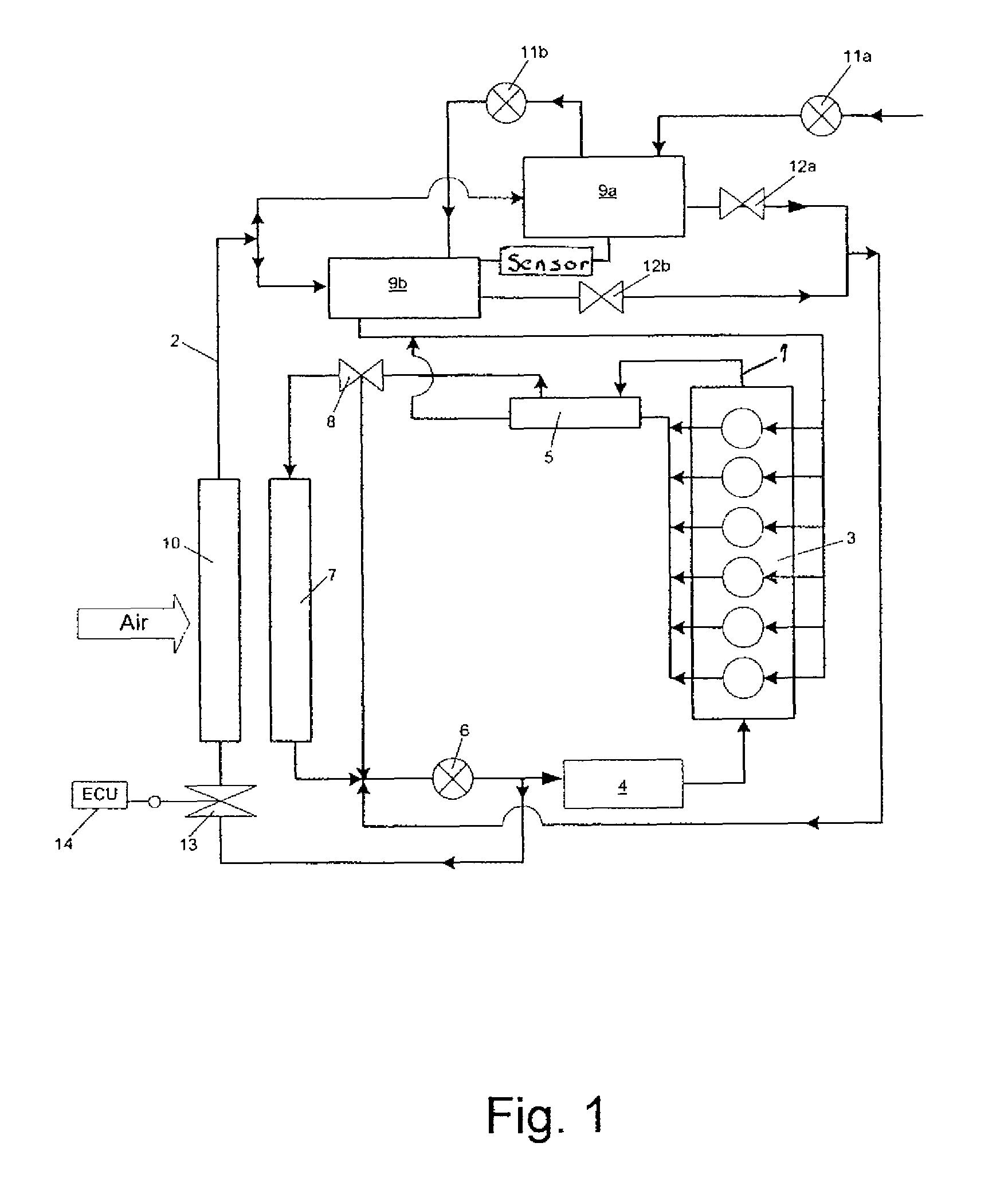
[0022]FIG. 1 shows a cooling system according to the present invention having a first cooling loop 1 designed as a high-temperature cooling loop and a second cooling loop 2 designed as a low-temperature cooling loop. In the exemplary embodiment shown of a motor vehicle cooling system, for example, as is used in modern utility vehicles, in particular in trucks and buses, an internal combustion engine 3, an oil heat exchanger 4, an exhaust gas heat exchanger 5, a coolant pump 6, and an air-cooled high-temperature heat exchanger 7 are hydraulically and thermally incorporated in the high-temperature cooling loop 1. Heat is dissipated from the above-mentioned vehicle components and transferred via the high-temperature heat exchanger 7 to the ambient air via the coolant conveyed in the first cooling loop 1, i.e., the high-temperature cooling loop.

[0023]A thermostat 8 is provided inside the first cooling loop 1, which thermostat regulates the coolant throughput through the high-temperature...


PUM


Abstract

A method and a system for cooling an internal combustion engine having charge air feed, which has a first and a second cooling loop, of which the first cooling loop is operated at a higher temperature level than the second cooling loop, and in which the charge air feed has at least one intercooling unit which is thermally coupled to the second cooling loop, having a controllable coolant throughput. The system includes at least one shutdown element in the second cooling loop for throttling the coolant throughput in the second cooling loop to 0 (zero). Coolant throughput may be shut down during the operation of the internal combustion engine as a function of an operating parameter of a vehicle component.

Description

BACKGROUND OF THE INVENTION[0001]1. Field of the Invention[0002]The present invention relates to a method and a system for cooling an internal combustion engine having charge air feed. The system includes a first and a second cooling loop, wherein the first cooling loop is operated at a higher temperature level than the second cooling circuit, and the charge air feed has at least one intercooling unit which is thermally coupled to the second cooling loop, in which a cooling throughput is controllable.[0003]2. Description of the Related Art[0004]Modern internal combustion engines, in particular diesel engines, typically have intercooling for cooling the air required for charging the internal combustion engine. Intercooling is required on one hand because of the heating up of the turbocharger due to the exhaust gases of the engine. The above-mentioned heating is caused by the joint arrangement of the turbine and the compressor on one shaft and consequently the thermal contact of the t...

Claims


Application Information

Patent Timeline
Patent Type & Authority Patents(United States)
IPC IPC(8): F02B29/04F02B33/44F02B33/00F01P9/00F01P7/02
CPCF01P3/12F01P7/165F01P7/167F02B29/0412F02B29/0443F02B29/0493F02B37/013F02M25/0731F01P2060/02F02M25/0711Y02T10/121Y02T10/146Y02T10/144F02M26/08F02M26/28Y02T10/12
Inventor RAAB, GOTTFRIEDKISLINGER, PETERKLINGER, HEIDRUN
Owner MAN TRUCK & BUS AG
Learn More