Carrier recovery circuit and demodulation circuit under quasi-coherent detection method

a carrier recovery circuit and detection method technology, applied in the direction of phase-modulated carrier systems, digital transmissions, electrical apparatus, etc., can solve the problem of bit error rate degradation, and achieve the effect of improving the bit error rate (ber) characteristics of the receiver and high-quality demodulation processing

Inactive Publication Date: 2012-09-06
NEC CORP
View PDF2 Cites 30 Cited by
  • Summary
  • Abstract
  • Description
  • Claims
  • Application Information

AI Technical Summary

Benefits of technology

[0022]According to the present invention, it is possible to improve bit error rate (BER) characteristics of a receiver in a digital radio communication system. Additionally, it is possible to achieve high-quality demodulation processing since it is possible to perform carrier recovery following variations of the C / N ratio.

Problems solved by technology

In a modulation method using phase information for data decision, phase errors (phase noise) that occur in a transmitter and a receiver may cause degradation of a bit error rate (BER).

Method used


Image

  • Carrier recovery circuit and demodulation circuit under quasi-coherent detection method
  • Carrier recovery circuit and demodulation circuit under quasi-coherent detection method
  • Carrier recovery circuit and demodulation circuit under quasi-coherent detection method

Examples


first embodiment

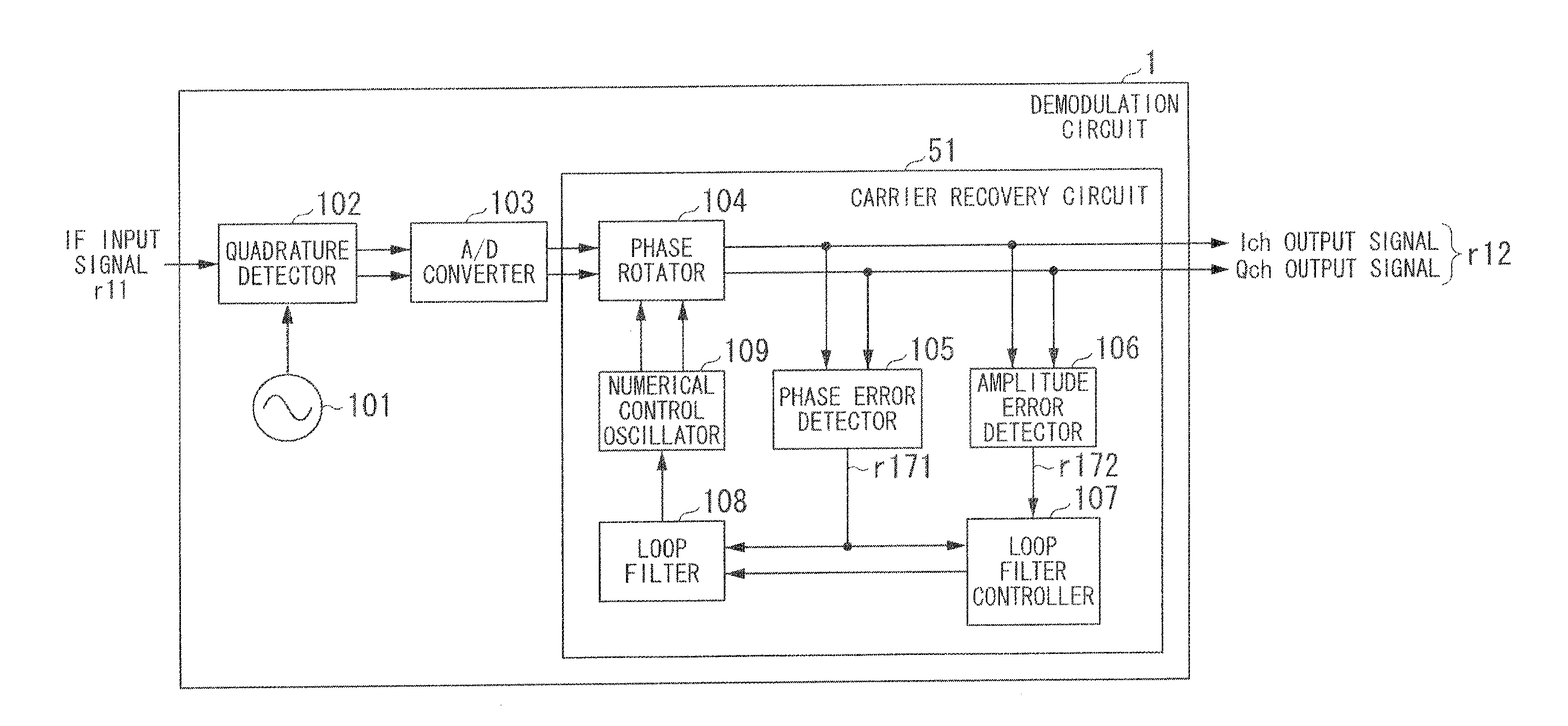
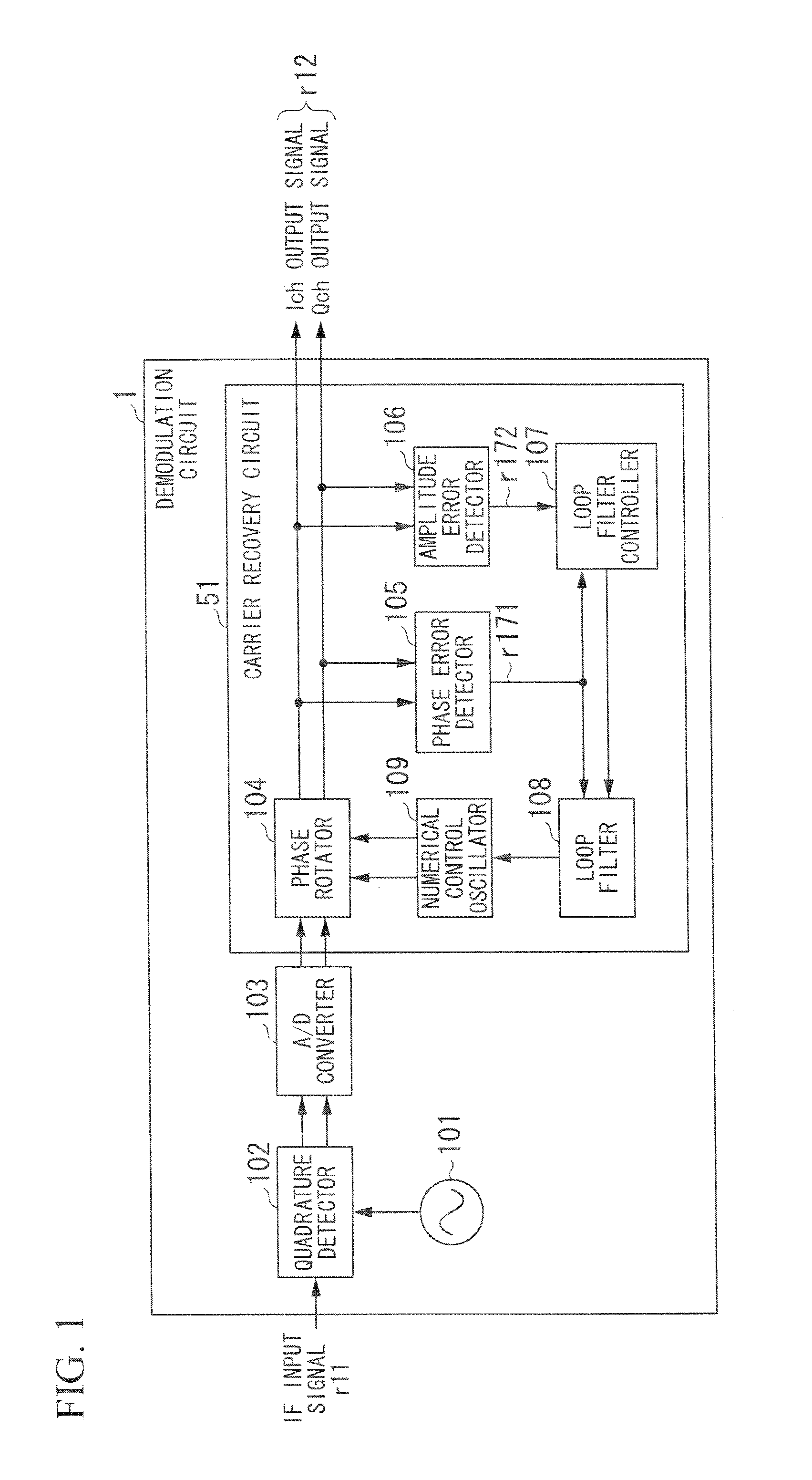
[0040]FIG. 1 is a block diagram showing the constitution of a demodulation circuit 1 according to a first embodiment of the present invention. The demodulation circuit 1 includes a reference oscillator 101, a quadrature detector 102, an A / D converter 103, and a carrier recovery circuit 51. The carrier recovery circuit 51 includes a phase rotator 104, a phase error detector 105, an amplitude error detector 106, a loop filter controller 107, a loop filter 108, and a numerical control oscillator (or a phase rotation controller) 109. The carrier recovery circuit 51 configures a carrier recovery loop equivalent to a PLL loop.

[0041]The reference oscillator 101 carries out free-running oscillation at a reference oscillation frequency (i.e. a fixed frequency) close to an oscillation frequency of a modulator so as to generate a frequency signal having the reference oscillation frequency, which is sent to the quadrature detector 102. The quadrature detector 102 performs quadrature detection, ...

second embodiment

[0090]FIG. 13 is a block diagram showing the constitution of a demodulation circuit 2 according to a second embodiment of the present invention. Herein, the constituent elements identical to those of the demodulation circuit 1 shown in FIG. 1 are designated by the same reference numerals. The demodulation circuit 2 is able to handle received signals with varying C / N ratios.

[0091]The demodulation circuit 2 includes the reference oscillator 101, the quadrature detector 102, the A / D converter 103, and a carrier recovery circuit 52. The carrier recovery circuit 52 includes the phase rotator 104, the phase error detector 105, the amplitude detector 106, the loop filter 108, and the numerical control oscillator 109. Additionally, the carrier recovery circuit 52 includes a secondary phase rotator 104-2, a secondary phase error detector 105-2, a secondary amplitude error detector 106-2, a secondary loop filter 108-2, a secondary numerical oscillator 109-2, and a loop filter controller 207.

[...


PUM


Abstract

A carrier recovery circuit, adapted to a demodulation circuit according to a quasi-coherent detection method for generating baseband signals by way of quadrature detection on a received signal having an intermediate frequency, rotates phases of baseband signals; detects a phase error and an amplitude error; controls a bandwidth of a loop filter based on its difference, eliminates a high-frequency component from the phase error; and performs phase rotation based on the phase error eliminating its high-frequency component. It expands the bandwidth of the loop filter when a difference between the phase error and the amplitude error is greater than a predetermined threshold, whilst reducing bandwidth of the loop filter upon determining that the amplitude error decreases due to a reduction of the bandwidth of the loop filter. This optimizes the bandwidth of the loop filter to follow variations of the C / N ratio of the received signal, improving bit error rate.

Description

TECHNICAL FIELD[0001]The present invention relates to a carrier recovery circuit and a demodulation circuit under a quasi-coherent detection method in a digital radio communication system.[0002]The present application claims priority on Japanese Patent Application No. 2009-254164 filed Nov. 5, 2009, the entire content of which is incorporated herein by reference.BACKGROUND ART[0003]Recently, various methods have been developed to improve the utilization efficiency of frequency bands and thereby achieve high-speed data communication in a digital radio communication system. For instance, methods of executing multi-valued digital modulation / demodulation according to modulation methods using phase information for data decision, such as quadrature amplitude modulation (QAM) and phase shift keying (PSK), have been known. In a modulation method using phase information for data decision, phase errors (phase noise) that occur in a transmitter and a receiver may cause degradation of a bit err...

Claims


Application Information

Patent Timeline
Patent Type & Authority Applications(United States)
IPC IPC(8): H04L27/22
CPCH04L27/2273H04L27/3827H04L2027/0081H04L2027/0069H04L2027/0057
Inventor SASAKI, EISAKUSATO, HIROTAKA
Owner NEC CORP
Why Eureka
Try Eureka