Encoding method, decoding method, and devices for same

Inactive Publication Date: 2008-01-31
FUJITSU LTD
View PDF8 Cites 34 Cited by
  • Summary
  • Abstract
  • Description
  • Claims
  • Application Information

AI Technical Summary

Benefits of technology

[0046] In light of the above, an object of this invention is to improve the error rate in encoding methods, decoding methods, and devices thereof in which dummy bits are added to information bits.
[0049] A further object of the invention is to define different codes by causing dummy bit patterns to be different, by this means to increase the freedom of code design and realize optimum codes, or to realize applications such as authentication of a plurality of terminals.
[0050] A further object of the invention is to avoid transmission of dummy bits from the transmitting side to the receiving side, and to reduce power consumption by the transmitter and receiver and reduce the band used by the transmission path.
[0051] A further object of the invention is to avoid transmission of dummy bits from the transmitting side to the receiving side, and to add dummy bits having maximum likelihoods on the receiving side to the received data when performing decoding, to reduce decoding errors.

Problems solved by technology

In particular, with respect to LDPC codes, if an attempt is made to improve characteristics for the same format (code length N, information length K), the weight distribution of the check matrix H must be optimized, and complicated numerical calculations become necessary.
Moreover, a code which satisfies a required code rate and can be implemented simply is not necessarily the optimal code in terms of characteristics.
However, in the rate matching method, a code having a low code rate is used as the mother code, and puncturing is employed in order to prepare other codes with higher code rates than this; but because puncturing entails deletion of information necessary for decoding, there is the problem that characteristics are greatly degraded.
Conversely, when a code having a higher code rate is prepared as the mother code, and a code with a lower code rate is to be prepared using repetition, decoding of a code with a shorter code length is performed, and so there is the problem that adequate characteristics are not obtained.
However, in the nulling method of the prior art, the all-“0”s which are added are also transmitted and subjected to decoding processing, so that reliability is lowered due to transmission errors, and there is the problem that decoding errors are increased.
(4) Further, the nulling method of the prior art is limited to an all-“0”s pattern, and there is the problem that freedom in defining the code is not used effectively.
However, there is the problem that the distribution does not provide optimum characteristics for the given code rate.
(6) In methods of the prior art entailing addition of filler bits, the filler bits are transmitted as-is, and so there is the problem that wasteful transmission costs are necessary.

Method used


Image

  • Encoding method, decoding method, and devices for same
  • Encoding method, decoding method, and devices for same
  • Encoding method, decoding method, and devices for same

Examples


first embodiment

(A) First Embodiment

[0110] (a) Encoding Method

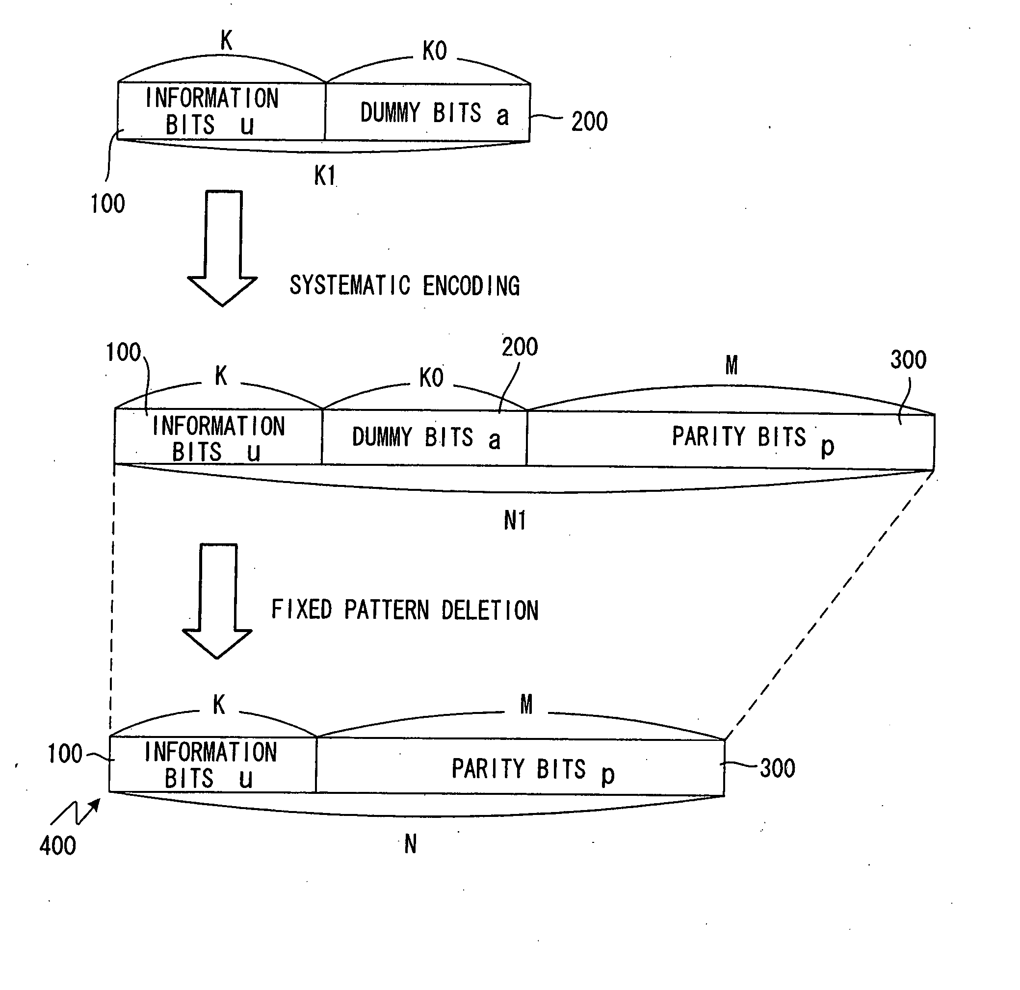
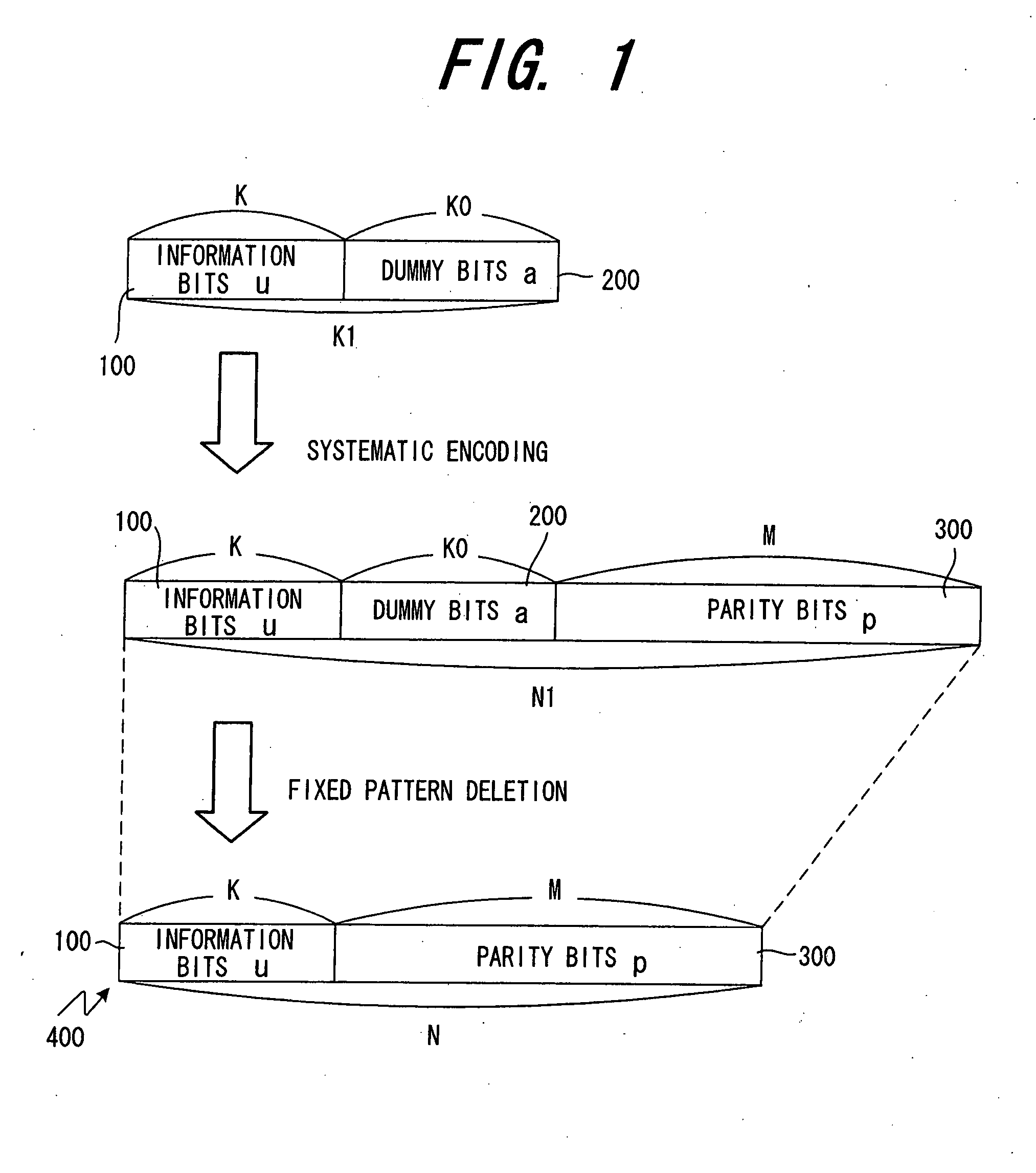
[0111]FIG. 1 explains an encoding method in a system to transmit and receive data using a systematic code, formed by adding parity alphabet elements to information alphabet elements. In the following explanation it is assumed that q=2, and in place of the term “alphabet”, the word “bit” is used; however, this invention is not limited to the case q=2.

[0112] K0 dummy bits in a prescribed pattern 200 are added to K information bits 100 to form K1 (=K+K0) information bits. The dummy bits are not limited to specific patterns such as an all-“1”s pattern or an all-“0”s pattern or a pattern such as 1010 . . . 10 which alternates “1”s and “0”s, and any prescribed pattern can be used. This is similarly true for all of the following embodiments as well.

[0113] Next, M parity bits 300, created using the K1 (=K+K0) information bits, are added to the K1 information bits to generate Ni (=K1+M) information bits (systematic encoding). Then, K0 dummy bi...

second embodiment

(B) Second Embodiment

[0176] In FIG. 1; a case in which dummy bits 200 are added randomly to information bits 100 was explained; more specifically, addition can be performed as follows. (A) of FIG. 10 is an example in which dummy-bits 200 are added all at once after information bits 100; (B) of FIG. 10 is an example in which dummy bits 200 are added all at once before information bits 100; and (C) of FIG. 10 is an example in which dummy bits 200 are added substantially uniformly to the information bits 100. Here, “substantially uniformly” means that there is no or almost no bias. As a method to add dummy bits substantially uniformly, for example, the rate-match pattern algorithm stipulated in 3GPP W-CDMA can be used to determine positions and add dummy bits. As a result of the dummy bit positions, the code characteristics change.

[0177] In particular, when an irregular LDPC code is used, among the columns of the check matrix H1 corresponding to the dummy bits, columns of the same wei...

third embodiment

(C) Third Embodiment

[0183] The code characteristics change depending on the dummy bit addition positions. For this reason, in the third embodiment the optimum dummy bit addition positions for an LDPC code are determined, and dummy bits are added at these positions.

[0184] The check matrix H1 when a fixed code is added is an M×N1 matrix, as shown in (C) of FIG. 3. Here M=N−K, and N1=N+K0. The check matrix H′ with no dummy bits added is the M×N matrix resulting by deletion of the QT portion from the check matrix H1. If an ideal situation is assumed, the encoding method of the first embodiment, in which dummy bits are inserted and encoding is performed, is no different in terms of characteristics from a method of deleting the columns (the QT portion) corresponding to the dummy bits from the check matrix H1, and using the M×N check matrix H′ thus obtained to decode the received N likelihood data items y.

[0185] Hence as shown in FIG. 13, when the known weight distribution of the N1×M ch...


PUM


Abstract

In a system in which systematic code, comprising information alphabet elements to which parity alphabet elements have been added, is transmitted and received, (1) K0 dummy alphabet elements are added to K information alphabet elements to generate first code of K1 (=K+K0) information alphabet elements; (2) M parity alphabet elements, created from the first-code of K1 information alphabet elements, are added to this first code of K1 information alphabet elements, and the K0 dummy alphabet elements are deleted to generate systematic code of N (=K+M) alphabet elements; and (3) the systematic code is received on the receiving side, the K0 dummy alphabet elements are added to the received systematic code, and decoding of the code of N1 alphabet elements obtained by adding the K0 dummy alphabet elements, is performed.

Description

BACKGROUND OF THE INVENTION [0001] This invention relates to an encoding method, a decoding method, and devices for these respective methods, in a system for transmission and reception of systematic codes, in which parity alphabet elements are added to the information alphabet elements. [0002] Systematic Codes and Block Codes [0003] In general, by reference to FIG. 35 encoding using an information alphabet element having q different values (a typical example is bit, q=2), is making a correspondence between a block I1 consisted of K information alphabet elements (information bits) and a block I2 consisted of N information alphabet elements wherein N is greater than K and an 1-to-1 association of all the possible patterns of the block I1 (of which there are qK) with patterns of the block I2 is established. [0004] Here, a code of block I2 which is configured such that K alphabet elements among the N alphabet elements are same as the original information alphabet elements is called a sy...

Claims


Application Information

Patent Timeline
IPC IPC(8): H03M13/00
CPCH03M13/1102H03M13/6356H03M13/2957
Inventor MIYAZAKI, SHUNJIOBUCHI, KAZUHISAYANO, TETSUYA
Owner FUJITSU LTD
Why Eureka
Try Eureka