
Ultra-thin membrane for chemical analyzer and related method for forming membrane

a chemical analyzer and ultra-thin technology, applied in the field of analytical systems, can solve the problems of limited mims instruments, limited use of high temperature as the sole approach, and labile analytes to degrad

Active Publication Date: 2012-08-16
INFICON GMBH
View PDF7 Cites 44 Cited by
  • Summary
  • Abstract
  • Description
  • Claims
  • Application Information

AI Technical Summary

Benefits of technology

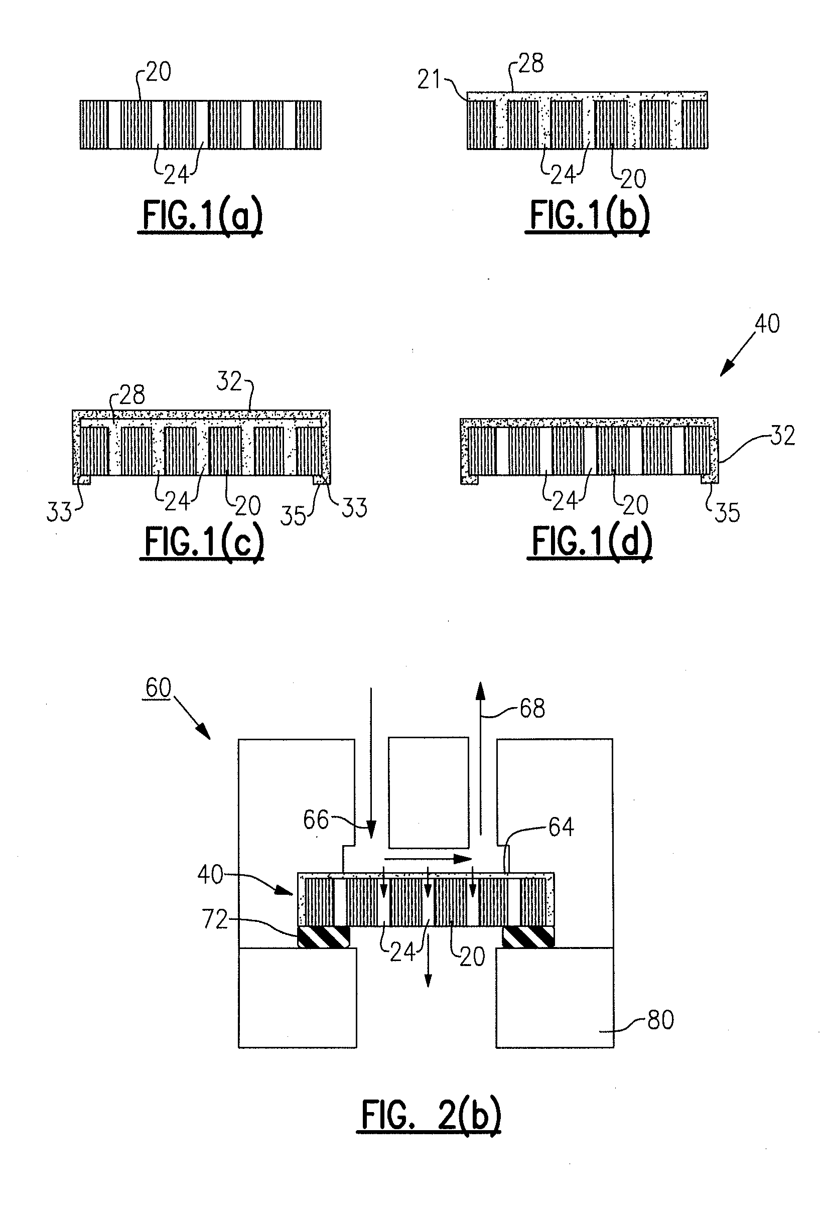
[0019]In one preferred embodiment, a two-part elastomer precursor for a semi-permeable material suitable for use as a membrane layer is cast using a spincoater designed such that the resulting film preferably overlaps the edges of the support structure and extends marginally onto the opposing face of the support structure. This membrane layer is then cured and the intermediate blocking layer is subsequently removed, such as by solvation in warm deionized water. As the blocking layer dissolves away, the semi-permeable membrane layer gently settles back down onto the support structure—held in place by the overlapping features of the polymer film. This process enables the creation of thin membranes, including ultra-thin membranes having thicknesses of approximately 0.5 μm, directly on a support structure. The combined assembly of these two parts (i.e., substrate and membrane layer) is ideal for MIMS of larger molecules, such as SVOCs, with all the benefits of reduced gas load on the mass spectrometer system.
[0026]Another advantage is that the formation of the herein described membranes improve the detection of various substances, such as contraband and explosive materials, using MIMS technology.
[0027]Ultra-thin and highly uniform membranes prepared as disclosed herein are also advantageous in that they can decrease the time required in fluid filtration applications. That is and for a given membrane area, higher fluxes are possible at a lower pressure differential, which can in turn increase the yield from the separation.

Problems solved by technology

One of the major limitations of MIMS instruments stems from the reality that analyte molecules must diffuse thorough the semi-permeable membrane before entering the ion source of the mass spectrometer.
One prior art approach involved heating the membrane directly with the photon flux from the ion source filament; however, there are limitations to using higher temperature as the sole approach.
Additionally, higher temperature may cause labile analytes to degrade.
Moreover and even at elevated temperatures, MIMS systems typically have time responses that are too slow for use as a gas chromographic detector in applications requiring the analysis of SVOCs and other large molecules.
In yet another prior art implementation, polymer films were coated onto AAO membranes, but no technique was provided to prevent this material from penetrating into the pores / channels as would be required to keep the membrane thin.
As previously mentioned above, thin membranes lack the mechanical strength required to support large pressure drops between the matrix environment and the vacuum of the mass spectrometer.
This lack of strength can cause deformation, which may result in unacceptable changes in device characteristics.
Thinner membranes can rupture, resulting in a loss of vacuum and damage to the mass spectrometer.
Creating the film directly on the support structure is often required for thin films because they lack the mechanical resiliency to withstand a mechanical transfer from production surface to support.
Mechanical assembly techniques which involve forming the film elsewhere and then moving it to the porous support structure are typically limited to strong films with a thickness in excess of 10 μm.
These steps may also create thin areas and other defects in thin membrane assemblies.
Thus and according to this design, the membrane did not serve to separate the high pressure on the matrix side from the low pressure vacuum of the mss spectrometer.
This system would thus fail to benefit from the largest advantage of a true MIMS system, which is a greatly reduced gas load on the pumping system compared to conventional inlet systems using capillaries or orifices.
Additionally, it seems unlikely that polypropylene fiber would be able to withstand high temperature operation, and it would not be as chemically inert as desired for many MIMS applications.

Method used


Image

  • Ultra-thin membrane for chemical analyzer and related method for forming membrane
  • Ultra-thin membrane for chemical analyzer and related method for forming membrane
  • Ultra-thin membrane for chemical analyzer and related method for forming membrane

Examples


Embodiment Construction

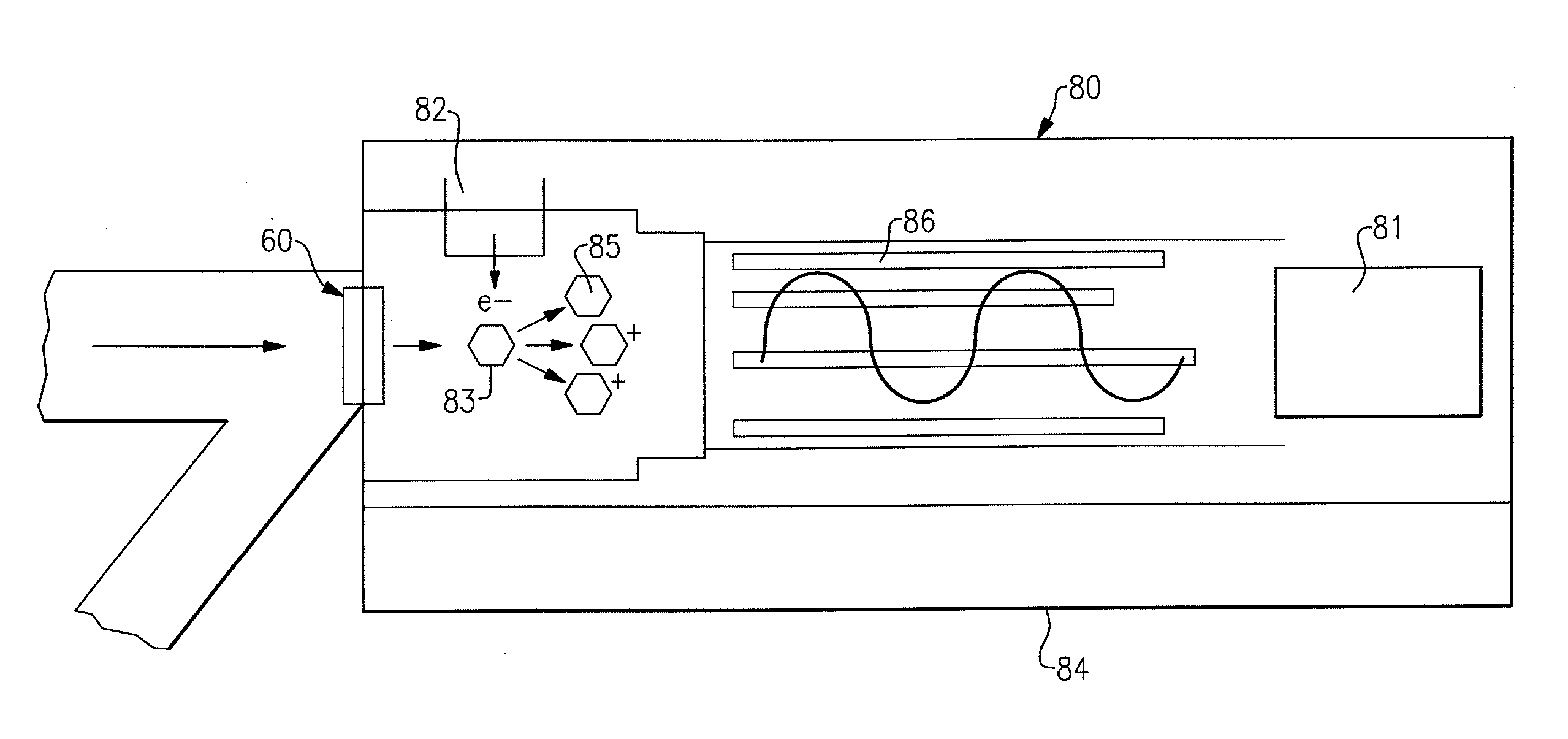
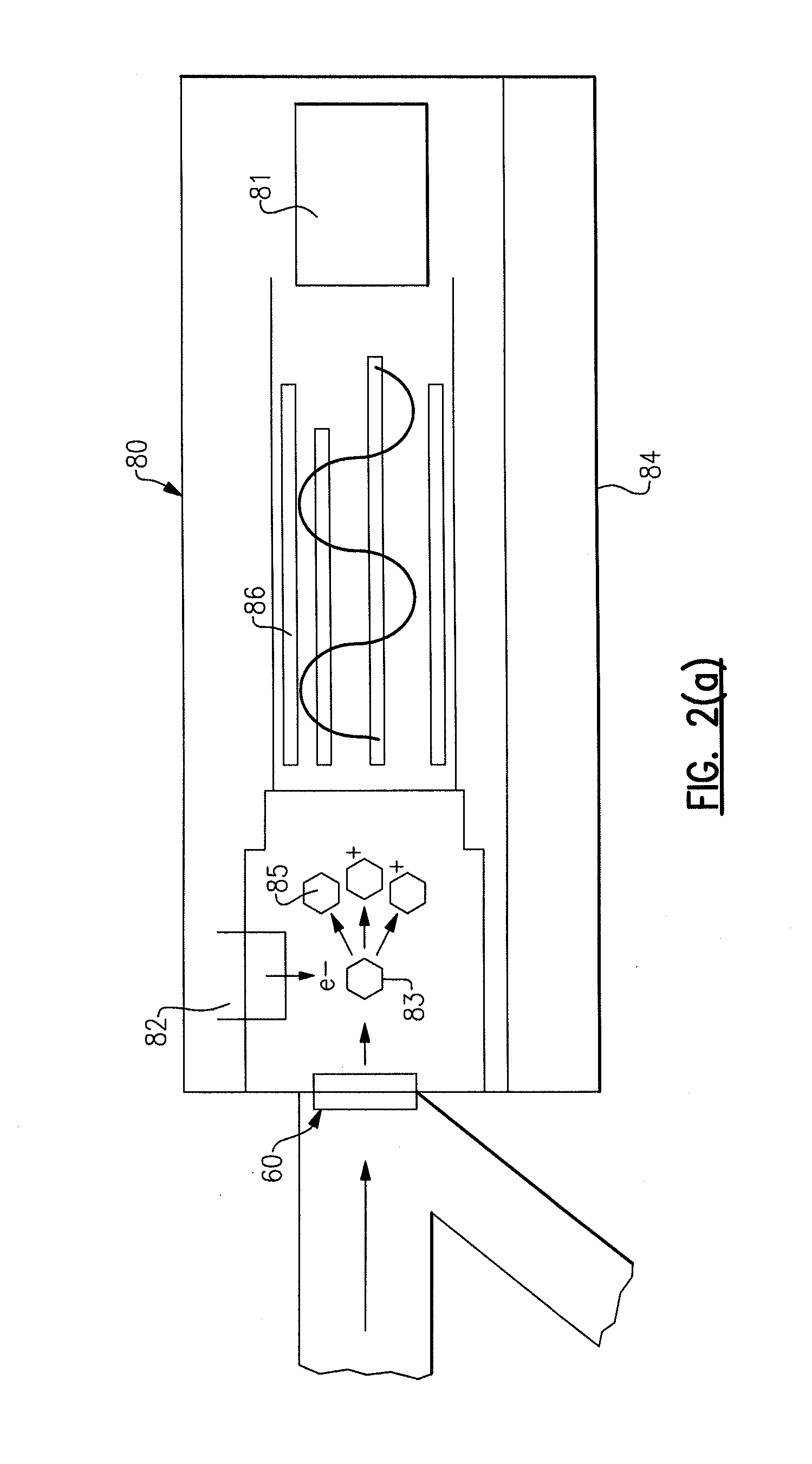
[0035]The following description relates to the formation of an ultra-thin membrane for applied use in membrane inlet mass spectrometry (MIMS) systems. It will be apparent from the following description that the membrane can be used suitably in other chemical analytical systems. Throughout the course of discussion, several terms such as “top”, “bottom” and the like are used in order to provide a suitable frame of reference in regard to the accompanying drawings. These terms are merely intended to provide clarity and are not intended to overly narrow the scope of the invention, including the claims, except where so specifically indicated.

[0036]Referring to FIG. 1(a), there is shown a porous substrate or support 20 having a plurality of pores 24. According to this specific version, the support 20 is a nano-porous substrate support such as those manufactured by Whatman Anodisc, a division of General Electric Healthcare. According to this specific embodiment, the substrate support 20 is ...


PUM


Abstract

A method for forming an ultra-thin membrane for use in a chemical analyzer such as a mass spectrometer includes the step of applying a sacrificial blocking layer onto a porous substrate, applying a semi-permeable membrane layer onto the sacrificial blocking layer, and removing the sacrificial blocking layer following cure of the membrane layer. In a preferred version, at least one of the blocking layer and the membrane layer are applied to the porous support by means of spin coating, though other deposition techniques can be employed.

Description

FIELD OF THE APPLICATION[0001]The application generally relates to the field of analytical systems and more specifically to the manufacture of an ultra-thin membrane for use in an interface assembly of a mass spectrometer.BACKGROUND OF THE APPLICATION[0002]The MIMS (Membrane Inlet or Interface Mass Spectrometry) method of sample introduction was first described by Hoch and Kok in 1963 and has been summarized in numerous recent articles. Most generally and according to this method, a semi-permeable membrane interface separates the gaseous or liquid sample matrix (e.g., carrier gas, ambient air, water) from the much lower pressure region that is created within a mass spectrometer. Analyte molecules pass through the semi-permeable membrane—the latter being typically formed solely from a silicone polymer—preferentially to the transport of molecules from a sample matrix. Thus and in comparison to mass spectrometry systems having direct sample inlets such as an orifice or capillary, a MIM...

Claims


Application Information

Patent Timeline
IPC IPC(8): B32B3/26B01D67/00H01J49/02
CPCB01D69/105H01J49/0427B01D2323/26Y10T428/249953Y10T428/249979
Inventor WOLCOTT, KATHERINE A.BRIGLIN, SHAWN M.
Owner INFICON GMBH
Learn More