
Integrated optofluidic system using microspheres

a technology of optofluorescence and microspheres, applied in fluid controllers, laboratory glassware, instruments, etc., can solve the problem that the complete integrated system cannot be fabricated using standard photolithography techniques

Active Publication Date: 2012-08-02
CORNELL UNIVERSITY
View PDF10 Cites 31 Cited by
  • Summary
  • Abstract
  • Description
  • Claims
  • Application Information

AI Technical Summary

Benefits of technology

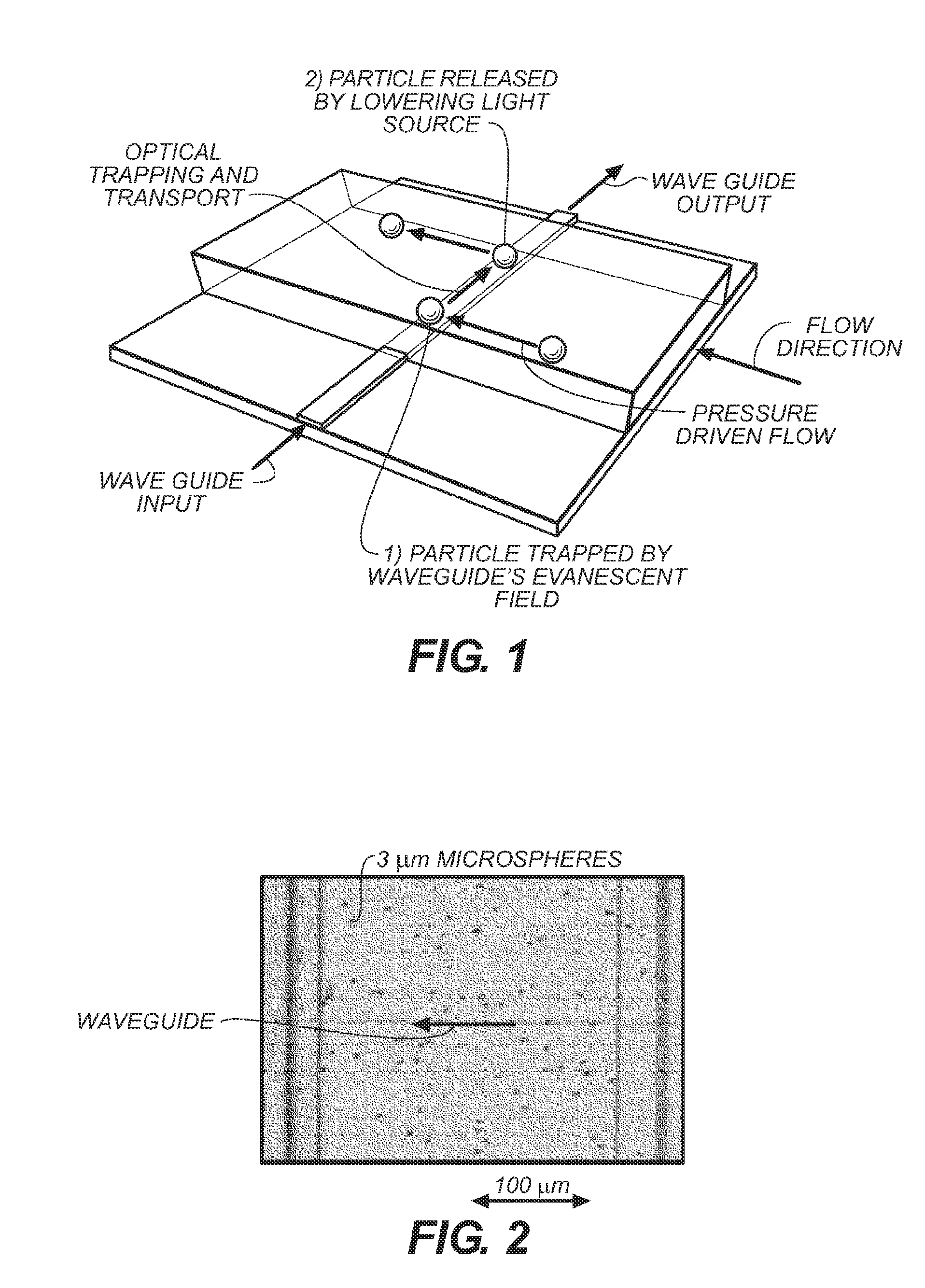
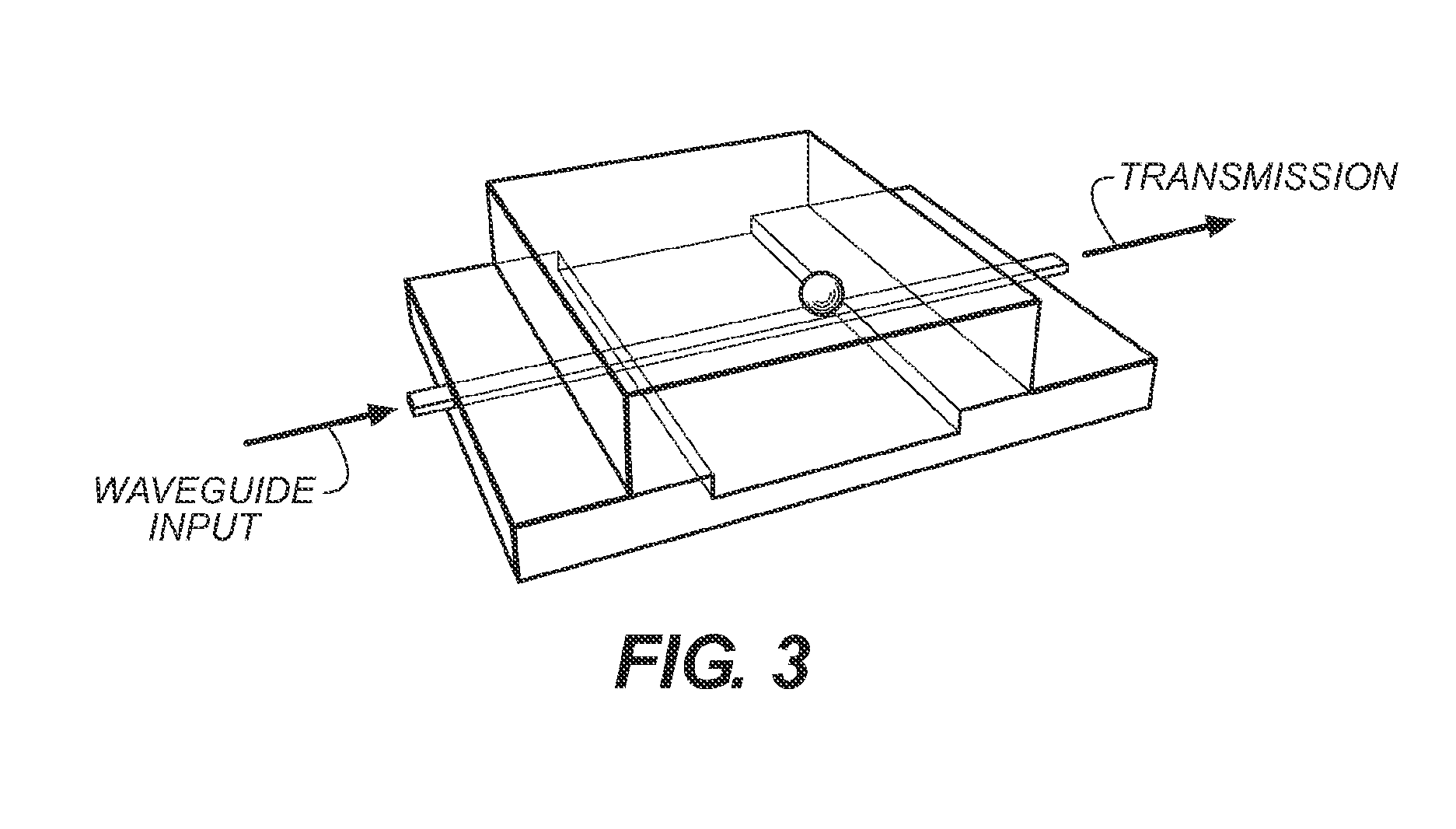
The patent describes an integrated optofluidic system that can trap and transport particles for analysis. The system includes a planar substrate, a microfluidic channel, a sensor region, and a waveguide integrated with the microfluidic channel. The system can detect and identify target analytes by trapping functionalized microspheres and measuring their resonant light scattering signature using a light source that produces light over an analytical wavelength range. The technical effects of this system include improved accuracy and sensitivity in particle analysis and the ability to detect and identify target analytes.

Problems solved by technology

However, coupling light into devices employing WGM detection and measurement is typically achieved using tapered optical fiber (F. Vollmer, D. Braun, A. Libchaber, M. Khoshsima, I. Teraoka, and S. Arnold, “Protein detection by optical shift of a resonant microcavity,” Appl. Phys. Lett. 80(21), 4057-4059 (2002)) or a prism, and therefore a complete integrated system cannot be fabricated using standard photolithography techniques.

Method used


Image

  • Integrated optofluidic system using microspheres
  • Integrated optofluidic system using microspheres
  • Integrated optofluidic system using microspheres

Examples


Embodiment Construction

[0096]For clarity of disclosure, and not by way of limitation, the detailed description of the invention is divided into the subsections set forth below.

[0097]5.1 Integrated Optofluidic System

[0098]An integrated optofluidic system for trapping and transporting particles for analysis is provided. In one embodiment, the optofluidic system comprises:[0099]a planar substrate;[0100]a microfluidic channel; and[0101]a waveguide, wherein the waveguide is integrated with the microfluidic channel

[0102]The integrated optofluidic system can be a stand-alone device or integrated into any suitable microfluidics platform known in the art. In certain embodiments, the integrated optofluidic system can form a component on a chip (e.g., a “lab-on-a-chip”) with other analysis capabilities. Particles and / or analytes that are analyzed by the integrated optofluidic system on the chip can be moved or pumped to other areas of the chip for further analysis or characterization.

[0103]The integrated optofluidic...


PUM

PropertyMeasurementUnit
widthaaaaaaaaaa
heightaaaaaaaaaa
diameteraaaaaaaaaa

Abstract

An integrated optofluidic system for trapping and transporting particles for analysis is provided comprising a planar substrate; a microfluidic channel; and a waveguide integrated with the channel. A microsphere particle in the integrated optofluidic system can act as a cavity, allowing light to circulate many thousands of times around the circumference of the microsphere. Optical trapping and transport is used for nanoscale positioning to excite the microsphere resonances. Sensitive measurements on molecules can be accomplished by monitoring changes in whispering gallery modes (WGMs) that propagate around the circumference of the microsphere. By using a broadband or supercontinuum light source, a microsphere can be trapped and many WGM resonances can be excited through the visible and near-infrared wavelengths simultaneously. After the resonances are measured using the waveguide transmission, the microsphere can be freed by decreasing the optical power and the process repeated with a different microsphere.

Description

CROSS-REFERENCE TO RELATED APPLICATIONS[0001]This application claims priority to and the benefit of co-pending U.S. provisional patent application Ser. No. 61 / 182,868, entitled “Integrated Biosensor Using Microspheres,” filed Jun. 1, 2009, which is incorporated herein by reference in its entirety.STATEMENT REGARDING FEDERALLY SPONSORED RESEARCH OR DEVELOPMENT[0002]The disclosed invention was made with government support under contract no. DGE-0654112 from the National Science Foundation. The government has rights in this invention.1. TECHNICAL FIELD[0003]The present invention relates generally to sensors integrated on planar substrates. The invention also relates to biosensors integrated on planar substrates. The invention further relates to optofluidic systems for trapping and transporting particles for analysis.2. BACKGROUND OF THE INVENTION[0004]Measurements of whispering gallery modes (WGMs) have been used successfully to detect the binding of single biomolecules (A. M. Armani, ...

Claims


Application Information

Patent Timeline
Patent Type & Authority Applications(United States)
IPC IPC(8): G01N21/75
CPCG01N21/05G01N21/53G01N2021/0346G01N2021/058G01N2021/7789G01N21/7703G01N21/47G01N21/63G01N33/53G01N35/08B01L3/502715B01L2400/0454G01N21/7746
Inventor NITKOWSKI, ARTHURLIPSON, MICHAL
Owner CORNELL UNIVERSITY
Learn More