Rotational molding machine and method
a molding machine and rotating technology, applied in the field of rotating molding machines and methods, can solve the problems of irregular surface area of tooling, and achieve the effects of reducing cycle time for parts production, uniform heating of mold tooling, and rapid and efficient operation
Inactive Publication Date: 2012-08-02
KONAL ENG & EQUIP
View PDF5 Cites 2 Cited by
- Summary
- Abstract
- Description
- Claims
- Application Information
AI Technical Summary
Benefits of technology
[0009]It is another object of this invention to heat the mold tooling uniformly, rapidly and efficiently to thereby minimize cycle time for production of parts.
Problems solved by technology
A continuing operational challenge and technical objective for this type of molding is to quickly heat the mold to a uniform temperature.
This is because the surface area of the tooling is irregular.
Method used
View moreImage
Smart ImageViewing Examples
Examples
example
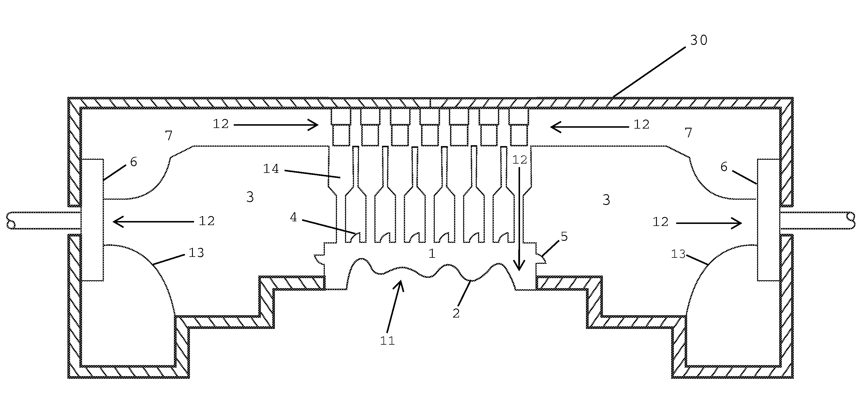
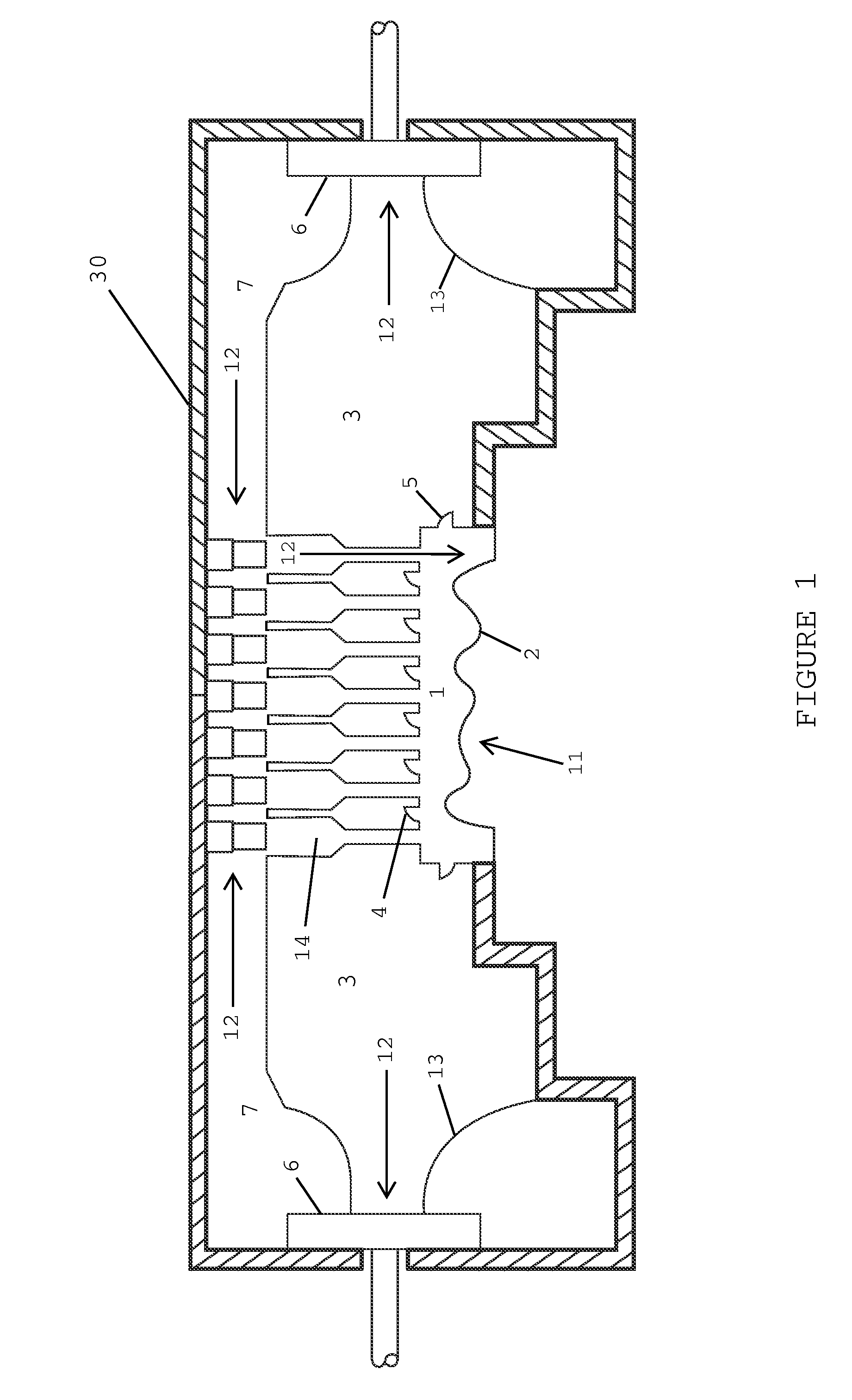
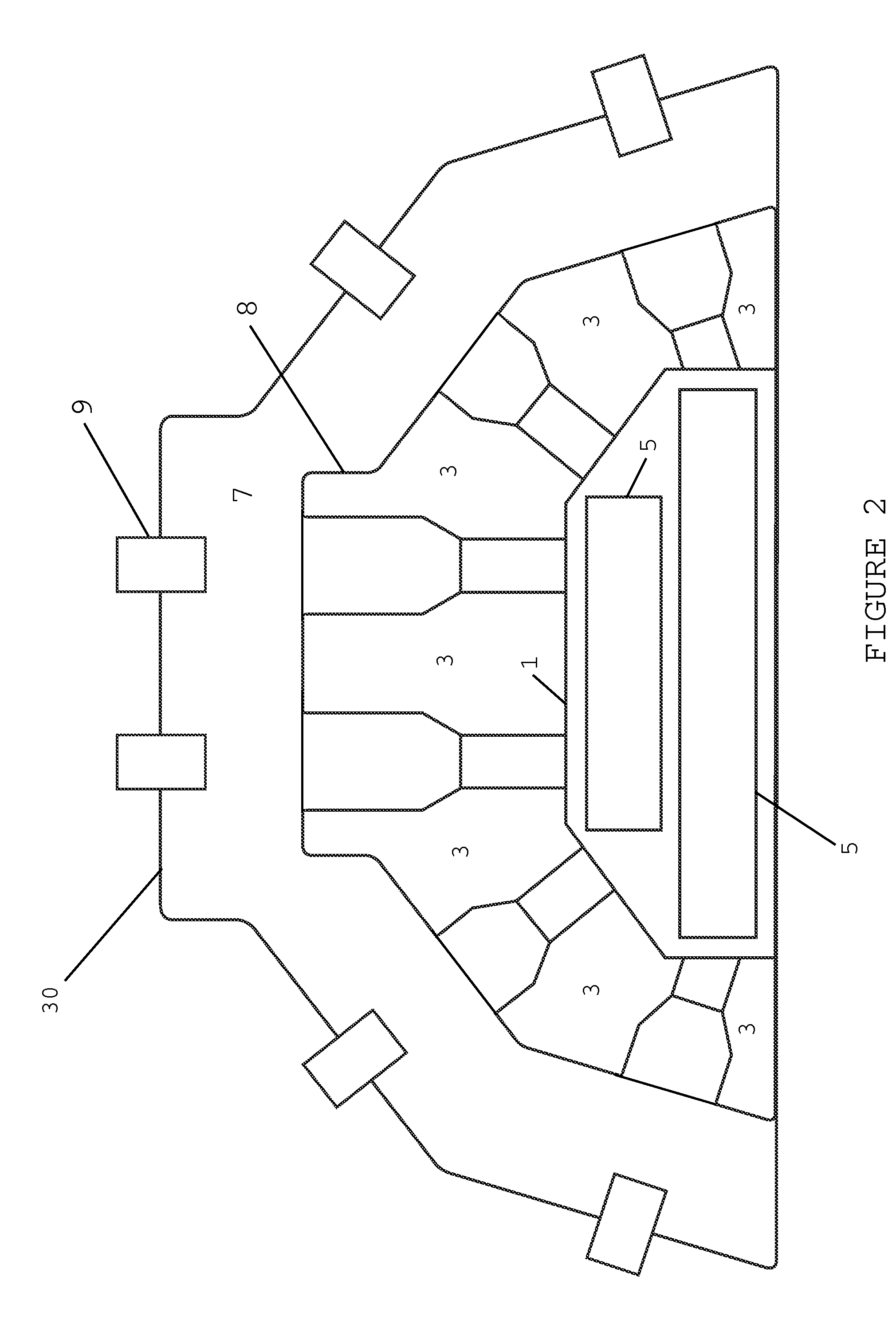
[0032]1. Combustion Conduits: An array of six rows around the periphery of the oven each row having seven combustion conduits as schematically illustrated in FIGS. 1 and 2. A total of 42 conduits and burners.[0033]2. Centrifugal fan: New York Blower Fan—Balanced for 1770 Rpm safe speed @ 800F Rated 65,000 CFM[0034]3. Fan Motor: 250 HP, 1800 RPM[0035]4. Gas burner: North American—Rated 192,000 Btu / HR
Login to View More PUM
| Property | Measurement | Unit |
|---|---|---|
| pressure | aaaaa | aaaaa |
| velocity | aaaaa | aaaaa |
| size | aaaaa | aaaaa |
Abstract
A molding machine apparatus and method for the production of thermoplastic skins or shells by means of what is generally known as rotational or slush molding. The tooling is heated uniformly, rapidly and efficiently by means of high velocity, hot air streams directed at the tooling which create turbulent flow on the surface of the tooling. The air stream is accelerated by means of adjustable nozzles and the air is circulated in the mold by means of a centrifugal fan.
Description
[0001]The invention relates to a molding machine apparatus and method for the production of thermoplastic skins or shells by means of what is generally known as rotational or slush molding. One example of a prior art apparatus is described in my issued U.S. Pat. No. 6,461,561.BACKGROUND OF THE INVENTION[0002]A continuing operational challenge and technical objective for this type of molding is to quickly heat the mold to a uniform temperature. This is because the surface area of the tooling is irregular. It is an object of this invention to heat the mold tooling uniformly, rapidly and efficiently to thereby minimize cycle time for production of parts.[0003]According to the present invention, a plurality of high velocity streams of heated air are directed at the irregularly shaped tooling in order to heat the mold to the operating temperature. In particular, an array of combustion conduits are arranged around the tooling which each direct the heated air at different parts of the tool...
Claims
Login to View More Application Information
Patent Timeline
 Patent Type & Authority Applications(United States)
IPC IPC(8): B29C41/46B29C41/18B29C41/34B29C33/04
CPCB29C33/046B29C41/46B29C41/18B29C41/04
Inventor MCNALLY, DOUGLAS JOHN
Owner KONAL ENG & EQUIP
Features
- R&D
- Intellectual Property
- Life Sciences
- Materials
- Tech Scout
- Unparalleled Data Quality
- Higher Quality Content
- 60% Fewer Hallucinations
Learn More Browse by: Latest US Patents, China's latest patents, Technical Efficacy Thesaurus, Application Domain, Technology Topic, Popular Technical Reports.
© 2025 PatSnap. All rights reserved.Legal|Privacy policy|Modern Slavery Act Transparency Statement|Sitemap|About US| Contact US: help@patsnap.com


