
Sheet handling apparatus with automatic removal of separating foil and method thereof

Active Publication Date: 2022-02-17
ASTES4 SA
View PDF0 Cites 0 Cited by
  • Summary
  • Abstract
  • Description
  • Claims
  • Application Information

AI Technical Summary

Benefits of technology

The patent describes a device that can quickly and reliably remove the foil between sheets of material, which helps to minimize the impact on the time it takes to withdraw the sheets.

Problems solved by technology

Removing the paper foil is necessary because its presence would make the gripping handler action of the withdrawing system ineffective.
Thus, the inconvenience of this system is immediately apparent, and that is the serious risk to which the operator is subjected, to various types of damage, of which a safety expert can easily become aware.
The attempts to automate this process have proved to be ineffective up to now for various reasons, in particular in view of the width of the paper foil and the fact that the presence of lubricants (for protecting metal sheets) tends to make the foil adhering persistently to the sheet below.
These systems, however, are conceived to help detach two sheets from each other, but they are not suitable for dragging a foil away from the top of the stack, because the compressed air blow acts locally and lifts an area around an edge.

Method used


Image

  • Sheet handling apparatus with automatic removal of separating foil and method thereof
  • Sheet handling apparatus with automatic removal of separating foil and method thereof
  • Sheet handling apparatus with automatic removal of separating foil and method thereof

Examples


Embodiment Construction

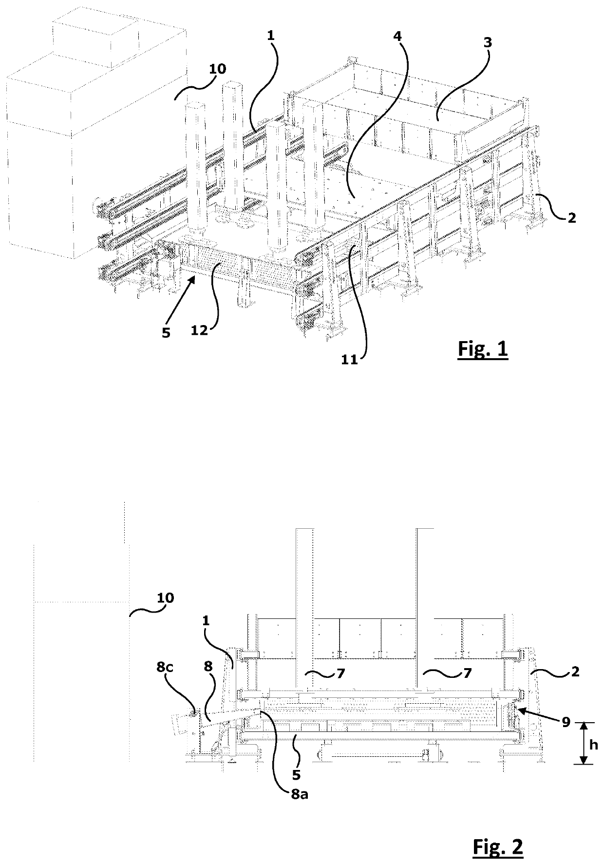
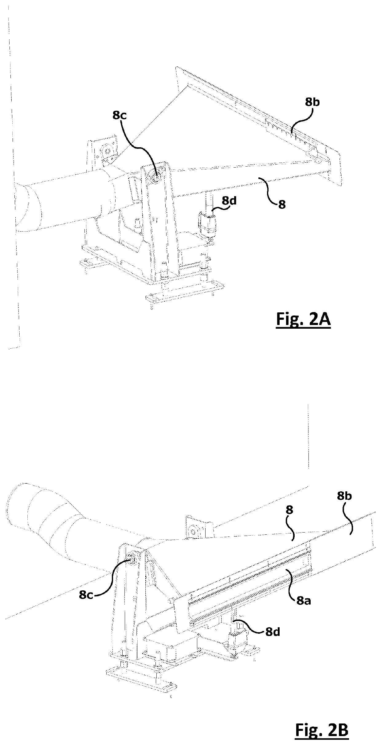
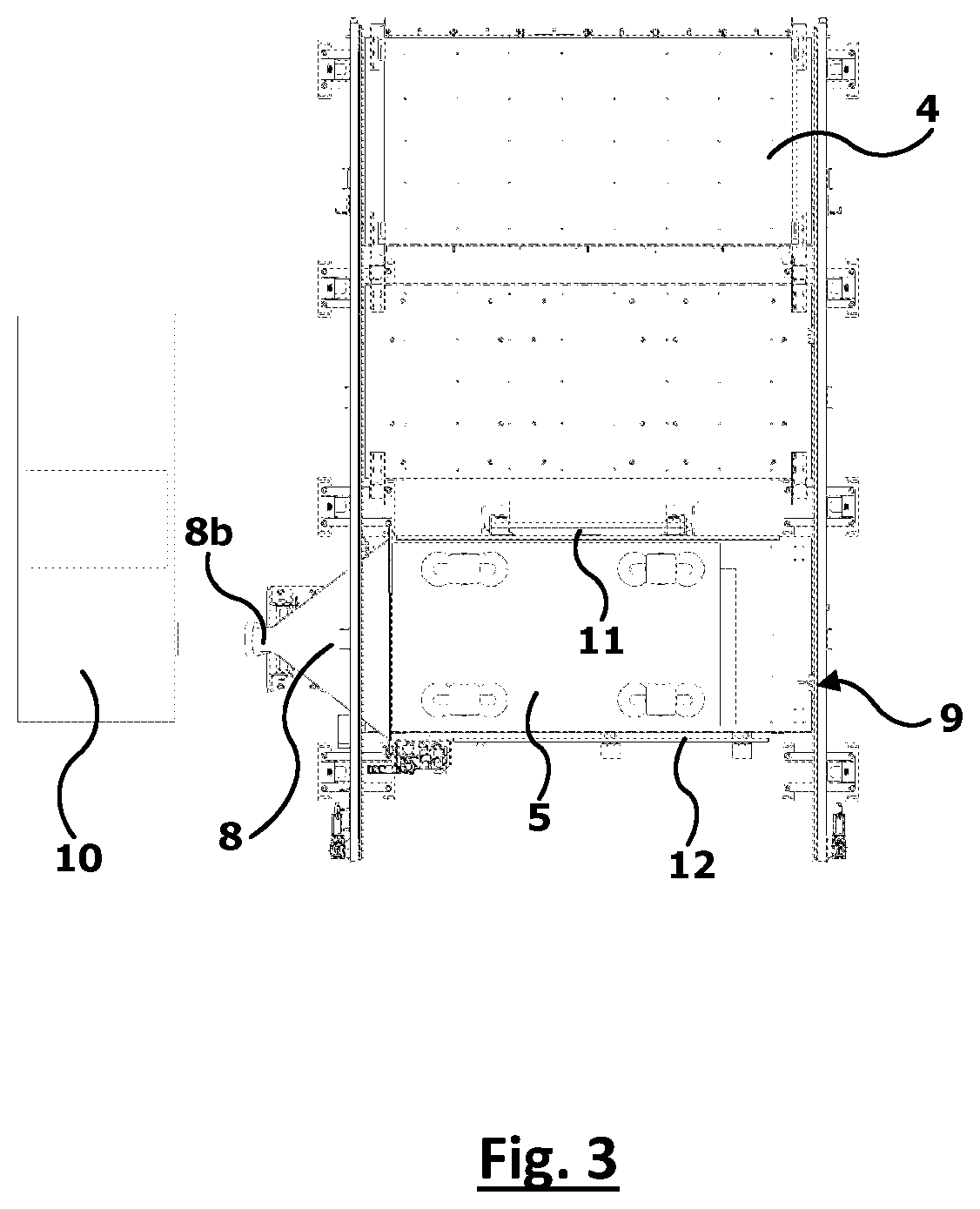
[0022]In FIGS. 1 and 2 a complex foil handling system is represented, of which only the part of interest for the purposes of the present invention will be described in detail.

[0023]More precisely, in FIG. 1 a transfer storage system is shown, provided with a two flanks frame 1, 2 on which three orders of translatable shelves or drawers 3, 4 and 5 are mounted movably by means of corresponding controlled movement rails 1a and 2a. The lower floor 5 of the storage is intended to house a pack of virgin metal sheets (not shown) waiting for being picket up one by one and transferred to a cutting centre.

[0024]Above the storage, sheet picking-up and transferring means are movably mounted; typically these picking-up means essentially comprise—as illustrated schematically in FIG. 2—a support carriage (not shown) on which gripping heads 7 (better visible in FIG. 5) are mounted, suitable for picking-up the metal sheet at the top of the stack and transferring it to the cutting centre.

[0025]Prefer...


PUM

PropertyMeasurementUnit
Heightaaaaaaaaaa
Timeaaaaaaaaaa
Flow rateaaaaaaaaaa

Abstract

A method and relative sheet handling apparatus apt to pick up sheets from a pack of sheets to be delivered to a cut-ting centre and for removing a separating foil between the sheets is described, including: a lifting and removing unit for a top sheet equipped with upper gripping heads; an air flow generating unit generating an air flow above the pack of sheets; and a control unit of the lifting unit, suitable for arranging the top sheet at a stasis height of up to 70 mm above the pack of sheet to define a suction chamber for the air flow generator.

Description

FIELD OF THE INVENTION[0001]The present invention relates to the SHEET handling field in cutting centres, in particular a metal sheet picking up withdrawing apparatus with automatic removal of the paper foil interposed between the metal sheets, as well as a relative withdrawal method.TECHNICAL BACKGROUND[0002]As is known, in metal sheet cutting centres—wherein, from a metal plate, single shaped pieces are obtained by means of various cutting devices (laser beam cutting, with oxygen lance, water jet, with plasma and so on)—there is a need to withdraw metal sheets from a warehouse in order to transfer them to the cutting machine.[0003]The metal sheets are typically large rectangular slabs (for example of 1500×3000 mm) of small thickness (for example from 0.5 to 25 mm) which are stacked in individual withdrawing warehouses according to a uniformity criterion, for example the same size and thickness.[0004]In the prior art there are already several apparatuses designed specifically for h...

Claims


Application Information

Patent Timeline
IPC IPC(8): B21D43/24B21D43/28B65G59/04B65G51/03
CPCB21D43/24B21D43/28B65G57/005B65G51/03B65G59/04B21D35/007B21D33/00
Inventor ZAFFARONI, ROBERTO
Owner ASTES4 SA
Learn More