
MR imaging system with cardiac coil and defibrillator

a technology of mr imaging and cardiac coil, which is applied in the field of mr imaging, can solve the problems of inability to inability to meet the position of cardiac rf coil, and significant risk of cardiac intervention, etc., and achieve safe external cardioversion or defibrillation. , high-quality cardiac mr imaging

Inactive Publication Date: 2012-06-28
KONINKLIJKE PHILIPS ELECTRONICS NV
View PDF3 Cites 0 Cited by
  • Summary
  • Abstract
  • Description
  • Claims
  • Application Information

AI Technical Summary

Benefits of technology

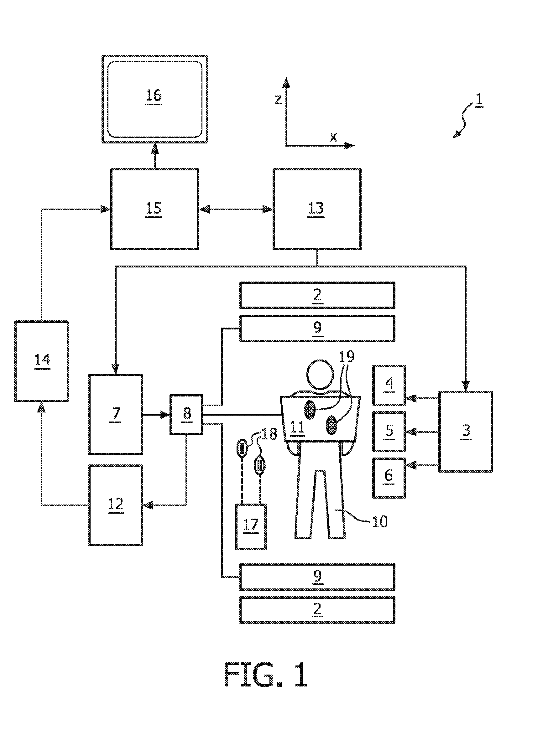
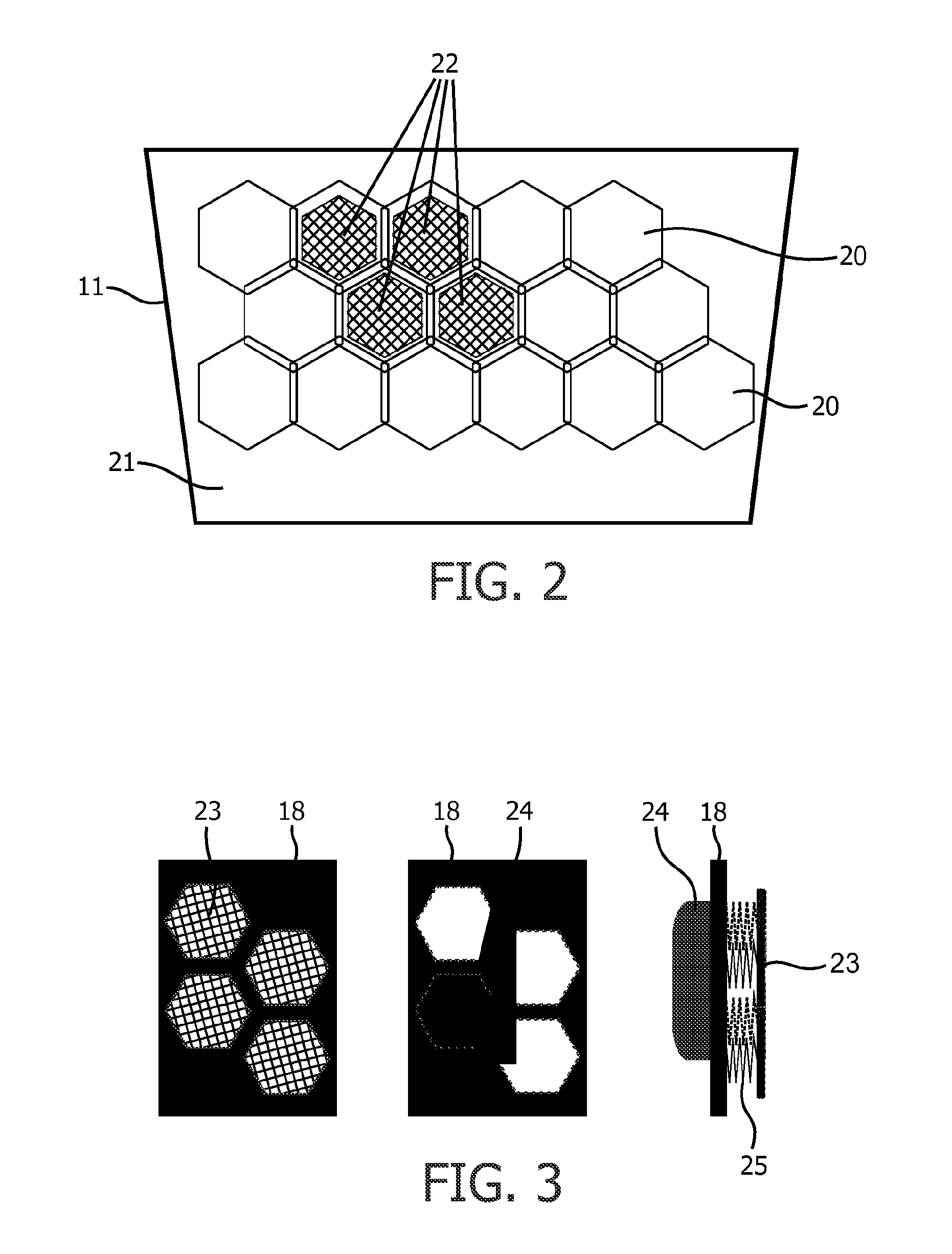
[0017]The magnetic resonance imaging system according to the invention comprises a defibrillator unit connected to (usually two) defibrillator electrodes fitting through openings in the cardiac RF coil placed on the chest of the examined patient. The cardiac RF coil of the magnetic resonance imaging system according to the invention provides access to the patient's skin in the chest region at the required defibrillation locations. This enables a safe defibrillation at any time during a MR-guided cardiac intervention. In particular, because of the openings in the cardiac RF coil there is no necessity to detach the cardiac RF coil from the chest of the patient for defibrillation in a case of emergency.
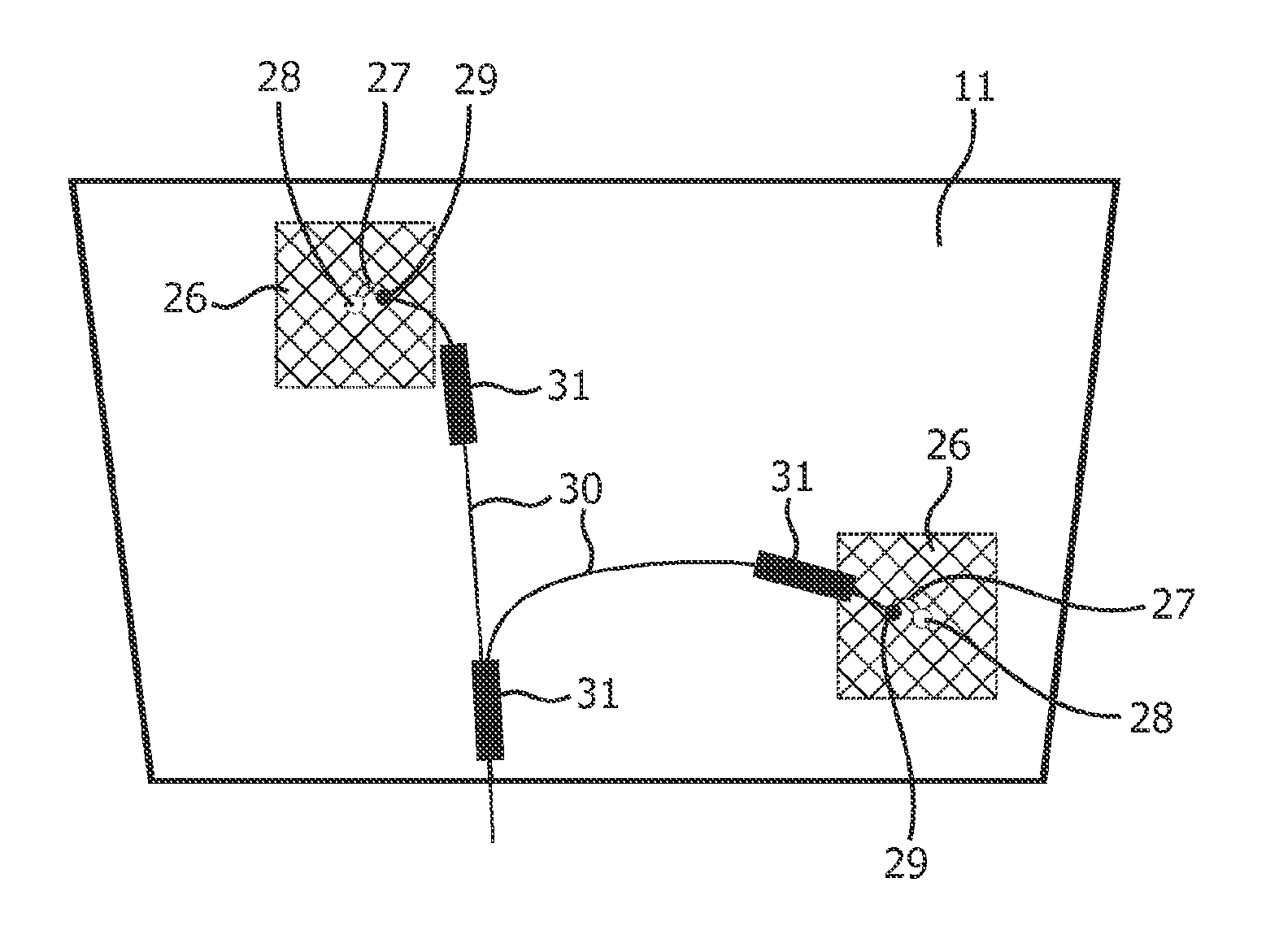
[0020]In accordance with a further aspect of the invention, adhesive defibrillator electrode pads connectable to the defibrillator unit via defibrillator cables may be used. In this variant of the invention, the defibrillator cables are affixed to the cardiac RF coil of the magnetic resonance imaging system. The defibrillator electrode pads have to be connected to the defibrillator unit via low impedance cables which are prone to RF-induced heating. Such heating effects can be suppressed by providing per se known resonant RF cable traps on the defibrillator cables. However, the cable traps become hot themselves during RF irradiation. By affixing the defibrillator cables to the cardiac RF coil, a cable routing is provided that avoids a close contact between the skin of the patient and the defibrillator cable and the cable traps. Hence, this variant of the invention also enables quick and safe defibrillation at any time during a MR-guided intervention without the risk of injury of the patient. In this context, it has to be considered that all cables present in the cardiac RF coil, including the defibrillator cables as well as the RF cables connecting the coil elements of the cardiac RF coil, exhibit mutual RF coupling. The coupling depends strongly on the routing geometry of the cables. The invention allows a fixed geometry of the complete cabling of the cardiac RF coil and of the positions of the cable traps. This geometry can be optimized once for efficiency and safety.
[0022]According to another preferred embodiment of the invention, the adhesive defibrillator electrode pads are constructed in such a manner that RF-induced or gradient-induced circular currents and resulting MR image artefacts are avoided. Each defibrillator electrode pad comprises one or more electrode foils that are formed in a pattern that avoids closed current paths. In this way, undesirable induced circular currents can be suppressed without inhibiting the current flow as required for defibrillation. The pattern of the electrode foil can be selected such that a relatively homogeneous distribution of the defibrillation current over the area of the pad is provided. Skin irritations by the defibrillation currents are prevented in this way. To this end, the pattern of the electrode foil may include a plurality of elongate sections extending radially outward from a centre. Such a generally star-shaped pattern is well suited for a defibrillation electrode pad according to the invention.
[0023]According to yet another preferred embodiment of the invention, the defibrillator unit is connectable to at least two defibrillator electrode pads via at least two defibrillator cables, wherein the defibrillator unit is configured to measure the impedance between the at least two defibrillator electrode pads. This configuration of the defibrillator unit enables the measurement of the impedance between the adhesive pads at regular intervals during the entire interventional MR imaging procedure. If the impedance is outside of a predefined range, the defibrillator unit may issue an alarm. Loosening of one of the electrode pads or the corresponding electrical connections can effectively be detected by measuring the impedance.
[0024]During an MR-guided cardiac intervention, the patient should be quickly removable from the examination volume of the MR imaging system and free access to the patient should be possible within short time. In an emergency situation, the intervention needs to be stopped immediately, for example in order to commence surgery or cardiopulmonary resuscitation. For this reason, the cardiac RF coil must be quickly removable from the patient at all times. Therefore, the cardiac RF coil should be constructed such that at least an anterior part of the cardiac RF coil is fastened to the posterior part and / or to the patient by a mechanism that can simply and quickly be released. Also the electrical connections connecting the adhesive defibrillator electrode pads to the integrated defibrillator cables of the cardiac RF coil should be constructed to release quickly at low force. For example, snap-fastener connections are well-suited for this purpose.

Problems solved by technology

Cardiac interventions, such as, for example, electrophysiology interventions, bear a significant risk of inducing atrial and ventricular tachycardia including fibrillation.
A major problem of presently existing systems is that the defibrillator paddle positions are incompatible with the position of standard cardiac RF coils.
This procedure requires a significant amount of time.
However, adhesive defibrillation pads may interfere with the MR imaging procedure such that it may not be practically feasible to continually couple the patient to the defibrillator unit.
Undesirable electromagnetic interactions of the switched magnetic field gradients and RF pulses being part of the imaging procedure with various components of the defibrillator electrode pads may occur.
This results in significant MR image artifacts.
Dangerous heating of the wire leads can injure the patient.

Method used


Image

  • MR imaging system with cardiac coil and defibrillator
  • MR imaging system with cardiac coil and defibrillator
  • MR imaging system with cardiac coil and defibrillator

Examples


Embodiment Construction

[0033]With reference to FIG. 1, a MR device 1 is shown. The device comprises superconducting or resistive main magnet coils 2 such that a substantially uniform, temporally constant main magnetic field is created along a z-axis through an examination volume.

[0034]A magnetic resonance generation and manipulation system applies a series of RF pulses and switched magnetic field gradients to invert or excite nuclear magnetic spins, induce magnetic resonance, refocus magnetic resonance, manipulate magnetic resonance, spatially and otherwise encode the magnetic resonance, saturate spins, and the like to perform MR imaging.

[0035]More specifically, a gradient pulse amplifier 3 applies current pulses to selected ones of whole-body gradient coils 4, 5 and 6 along x, y and z-axes of the examination volume. A RF transmitter 7 transmits RF pulses or pulse packets, via a send- / receive switch 8, to a whole-body volume RF coil 9 to transmit RF pulses into the examination volume. A typical MR imaging...


PUM


Abstract

The invention relates to a magnetic resonance imaging system comprising a main magnet coil (2) for generating a uniform, steady magnetic field within an examination volume, a number of gradient coils (4, 5, 6) for generating switched magnetic field gradients in different spatial directions within the examination volume, at least one cardiac RF coil (11) for transmitting RF pulses to and / or receiving MR signals from the chest region of a body (10) of a patient positioned in the examination volume, a control unit (13) for controlling the temporal succession of RF pulses and switched magnetic field gradients, and a reconstruction unit (15) for reconstructing a MR image from the MR signals. In order to enable quick and safe defibrillation at any time during a MR imaging procedure, the invention proposes that at least one opening (19, 22) is provided in the cardiac RF coil (11), through which opening (19, 22) a portion of the skin surface in the chest region of the body (10) is accessible, wherein the magnetic resonance imaging system further comprises a defibrillator unit (17) connected to at least one defibrillator electrode (23) fitting through the at least one opening (19, 22) provided in the cardiac RF coil (11). Alternatively, the invention proposes that at least one defibrillator cable (30) is affixed to the cardiac RF coil (11), wherein the defibrillator unit (17) is connectable to at least one defibrillator electrode pad (26) via the at least one defibrillator cable (30).

Description

FIELD OF THE INVENTION[0001]The invention relates to the field of magnetic resonance (MR) imaging. It concerns a MR imaging system comprising a cardiac RF coil and a defibrillator unit. The invention also relates to a cardiac RF coil adapted to be used with a defibrillator unit.[0002]Image-forming MR methods which utilize the interaction between magnetic fields and nuclear spins in order to form two-dimensional or three-dimensional images are widely used nowadays, notably in the field of medical diagnostics, because for the imaging of soft tissue they are superior to other imaging methods in many respects, do not require ionizing radiation and are usually not invasive.BACKGROUND OF THE INVENTION[0003]According to the MR method in general, the body of the patient to be examined is arranged in a strong, uniform magnetic field whose direction at the same time defines an axis (normally the z-axis) of the co-ordinate system on which the measurement is based. The magnetic field produces d...

Claims


Application Information

Patent Timeline
IPC IPC(8): A61B5/055A61N1/39A61N1/04
CPCG01R33/3415G01R33/28A61B5/0044
Inventor WEISS, STEFFENDAVID, BERNDLIPS, OLIVERKRUEGER, SASCHA
Owner KONINKLIJKE PHILIPS ELECTRONICS NV
Learn More