
Reflector, optical element, interferometer system, stage device, exposure apparatus, and device fabricating method

a technology of interferometer system and exposure apparatus, which is applied in the field of refractive elements, interferometer system, stage device, exposure apparatus, etc., can solve the problems of affecting measurement, difficult to secure a location for installing downflow equipment, and requiring an increase in the size of the apparatus, so as to reduce the incidence of detection failure and measurement error.

Inactive Publication Date: 2012-05-24
NIKON CORP
View PDF0 Cites 4 Cited by
  • Summary
  • Abstract
  • Description
  • Claims
  • Application Information

AI Technical Summary

Benefits of technology

Enables precise position measurement of a movable stage without increasing the apparatus size and reduces the incidence of detection failures and measurement errors caused by changes in the stage's attitude, ensuring high precision.

Problems solved by technology

With a constitution wherein a reflecting plate is provided above a movable stage, it is difficult to secure a location for installing downflow equipment.
In addition, if a measuring instrument, which is used to measure the position of the projection optical system and the wafer, is disposed above the movable stage in order to avoid the reflecting plate, then there is a risk that this will invite an increase in the size of the apparatus.
With such an interferometer system, the optical path length of the beam is comparatively long, and changes in the attitude of the stage therefore tend to affect the measurement result.
For example, a change in the inclination of the stage results in a comparatively large positional deviation of the beam that returns from the stage and / or a comparatively large angular deviation in the return direction, and there is consequently a possibility that this will invite a detection failure and / or measurement error.

Method used


Image

  • Reflector, optical element, interferometer system, stage device, exposure apparatus, and device fabricating method
  • Reflector, optical element, interferometer system, stage device, exposure apparatus, and device fabricating method
  • Reflector, optical element, interferometer system, stage device, exposure apparatus, and device fabricating method

Examples


Embodiment Construction

[0046]The following explains the embodiments of the present invention, referencing FIG. 1 through FIG. 23.

[0047]First, the following explains an embodiment wherein a stage apparatus according to the present invention is adapted to a wafer stage of an exposure apparatus, and a reflecting member according to the present invention is provided to the wafer stage.

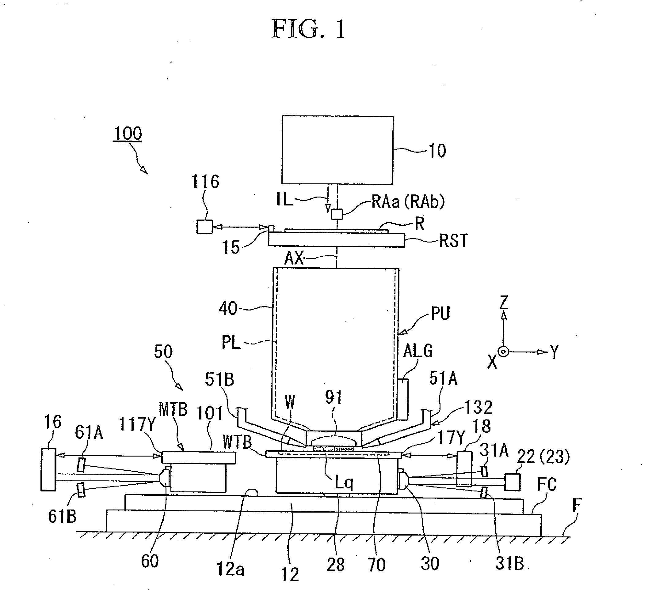
[0048]FIG. 1 shows a schematic block diagram of an exposure apparatus 100 of the present embodiment. The exposure apparatus 100 is a step-and-scan type projection exposure apparatus, i.e., a so-called scanning stepper. The exposure apparatus 100 comprises: an illumination system 10; a reticle stage RST that holds a reticle R, which serves as a mask; a projection unit PU; a stage apparatus 50, which comprises a wafer stage WST and a measurement stage MST; and a control system therefore. A wafer W is mounted on the wafer stage WST—

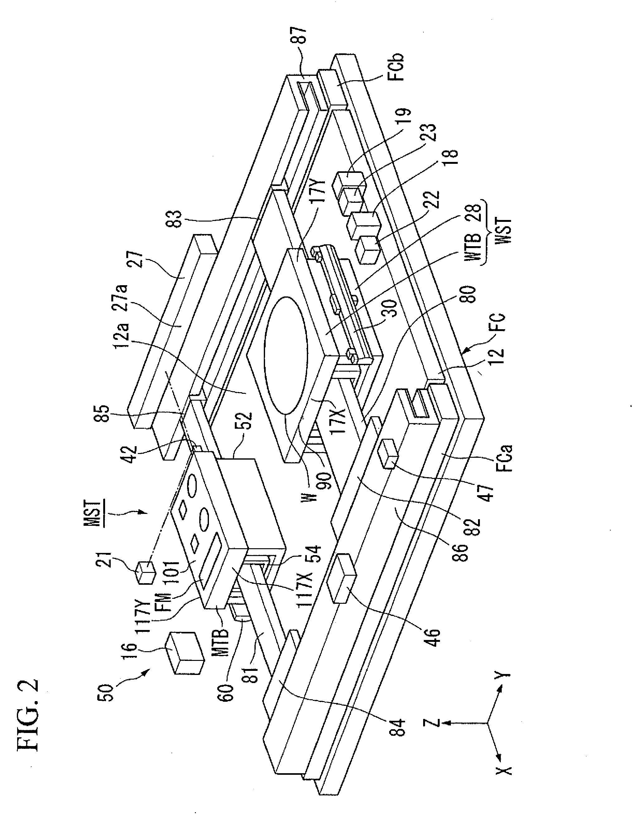
[0049]First, the stage apparatus 50 will be explained. The stage apparatus 50 comprises: a frame cast...


PUM


Abstract

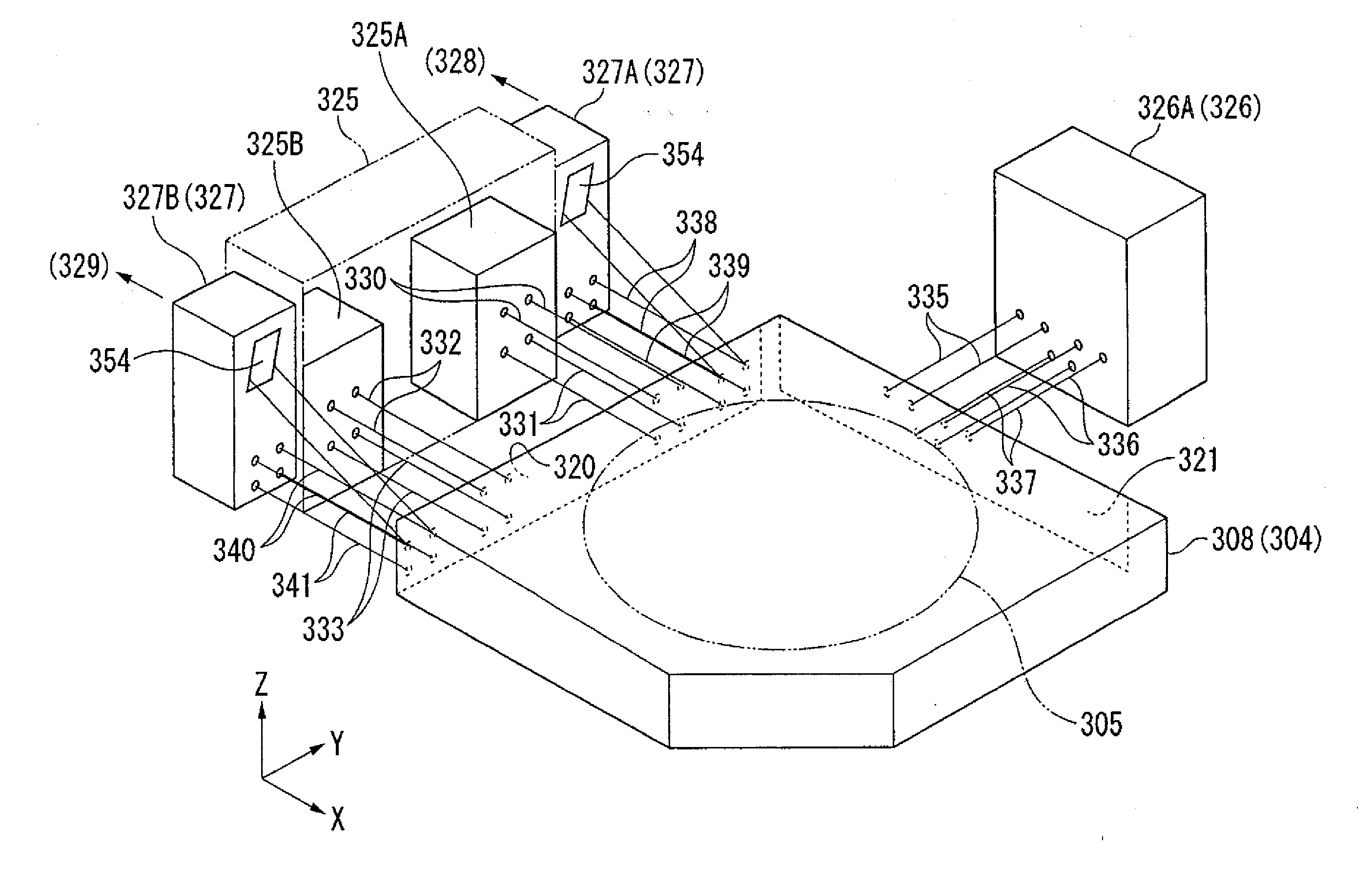
A reflecting member has: a first reflecting surface, which extends in a second direction that includes a first direction component; a second reflecting surface, which extends in a third direction that includes the first direction component, that is substantially symmetric to the first reflecting surface; and a third reflecting surface, which extends in a fourth direction, that is substantially orthogonal to the first direction.

Description

CROSS-REFERENCE TO RELATED APPLICATION[0001]This application is a divisional of U.S. patent application Ser. No. 11 / 475,034, filed Jun. 27, 2006, which claims priority to Japanese Patent Application Nos. 2005-188228 and 2005-188269, both filed on Jun. 28, 2005, the disclosures of which are hereby incorporated by reference in their entirety.BACKGROUND OF THE INVENTION[0002]1. Field of the Invention[0003]The present invention relates to a reflector, an optical element, an interferometer system, a stage device, an exposure apparatus, and a device fabricating method.[0004]2. Description of Related Art[0005]In a process of fabricating an electronic device, such as a semiconductor device or a liquid crystal display device, a projection exposure apparatus is used that projects a pattern image of a mask or a reticle (hereinafter, generically referred to as a reticle), wherein a pattern is formed through a projection optical system onto each projection region (shot region) on a substrate (su...

Claims


Application Information

Patent Timeline
Patent Type & Authority Applications(United States)
IPC IPC(8): G01B11/14G01B9/02B01J19/08G01B11/24
CPCG03F7/70775G02B5/08G01B9/02G03F7/70308
Inventor SHIBAZAKI, YUICHIHIDAKA, YASUHIRO
Owner NIKON CORP
Learn More