
Method and computing system for designing a sheet-metal-forming process

a technology of sheet metal and design system, applied in the direction of cad techniques, total factory control, instruments, etc., can solve the problems of material stretching too much, cracks or tears, surface lows or grooves, etc., and achieve the effect of not being stretched sufficiently

Active Publication Date: 2012-05-17
NETABTAL MASCHEN
View PDF11 Cites 25 Cited by
  • Summary
  • Abstract
  • Description
  • Claims
  • Application Information

AI Technical Summary

Benefits of technology

"The patent describes a method and system for designing a sheet-metal-forming process by using a processor and a numerical model of the part. The system can automatically determine problem zones of the part by analyzing the forming process and can also display a visual representation of the part with the problem zones highlighted. The system can also allow the user to manually define problem zones and to assign them a type and problem criterion. The technical effect of this patent is to provide a more efficient and consistent way of designing sheet-metal-forming processes by identifying and addressing problem zones of the part."

Problems solved by technology

For example, the material may be stretched too much and exhibit cracks or tears, develop wrinkles, surface lows or grooves, not be sufficiently stretched, exhibit shape deviations due to springback, etc.
Issues can be small faces that do not match Finite Element Analysis (FEA) requirements.

Method used


Image

  • Method and computing system for designing a sheet-metal-forming process
  • Method and computing system for designing a sheet-metal-forming process
  • Method and computing system for designing a sheet-metal-forming process

Examples


Embodiment Construction

Terms Used

[0076]Formed part: For the sake of brevity, the terms “formed part” or simply “part” shall be used instead of “formed sheet-metal part” throughout the present application.

Parameters: Parameters may be of the following types:[0077]simulation parameters: may include nominal parameters plus parameters defining a stochastic variation around the nominal parameters. They may be controllable and noncontrollable (disturbances). They comprise[0078]process parameters of the process being simulated; and[0079]geometry of tools and / or parts; and[0080]material parameters of the material being formed.[0081]control parameters (of numerical simulation).[0082]analysis parameters for post-simulation analysis.

Input parameters: Input parameters are the inputs to the design process, that is, on the one hand, the simulation parameters and on the other hand a model of the geometry of the part, that is, either a target geometry after the forming process, or an intermediate geometry, resp. the tool...


PUM

PropertyMeasurementUnit
shapeaaaaaaaaaa
thicknessaaaaaaaaaa
elastic propertiesaaaaaaaaaa

Abstract

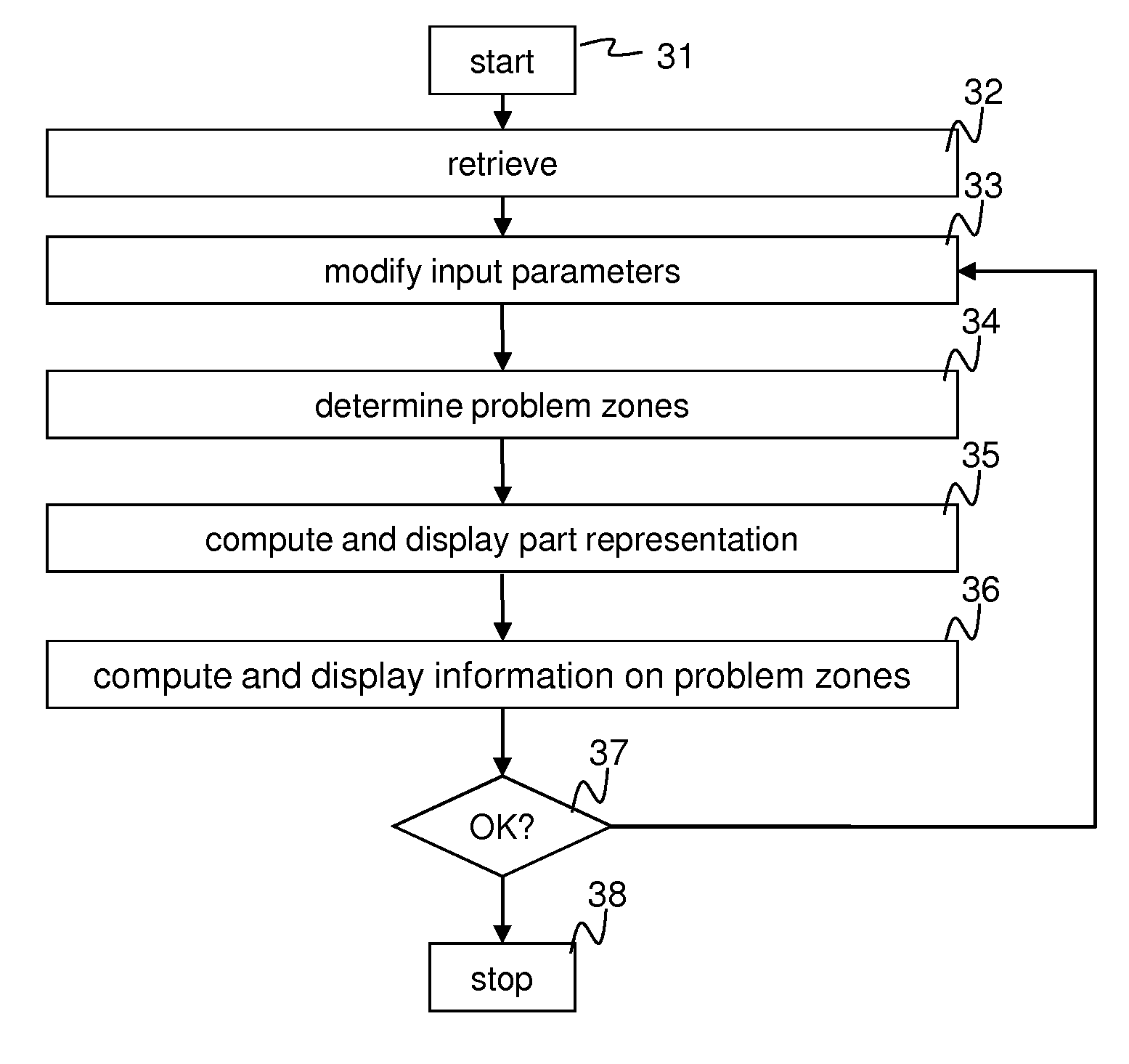
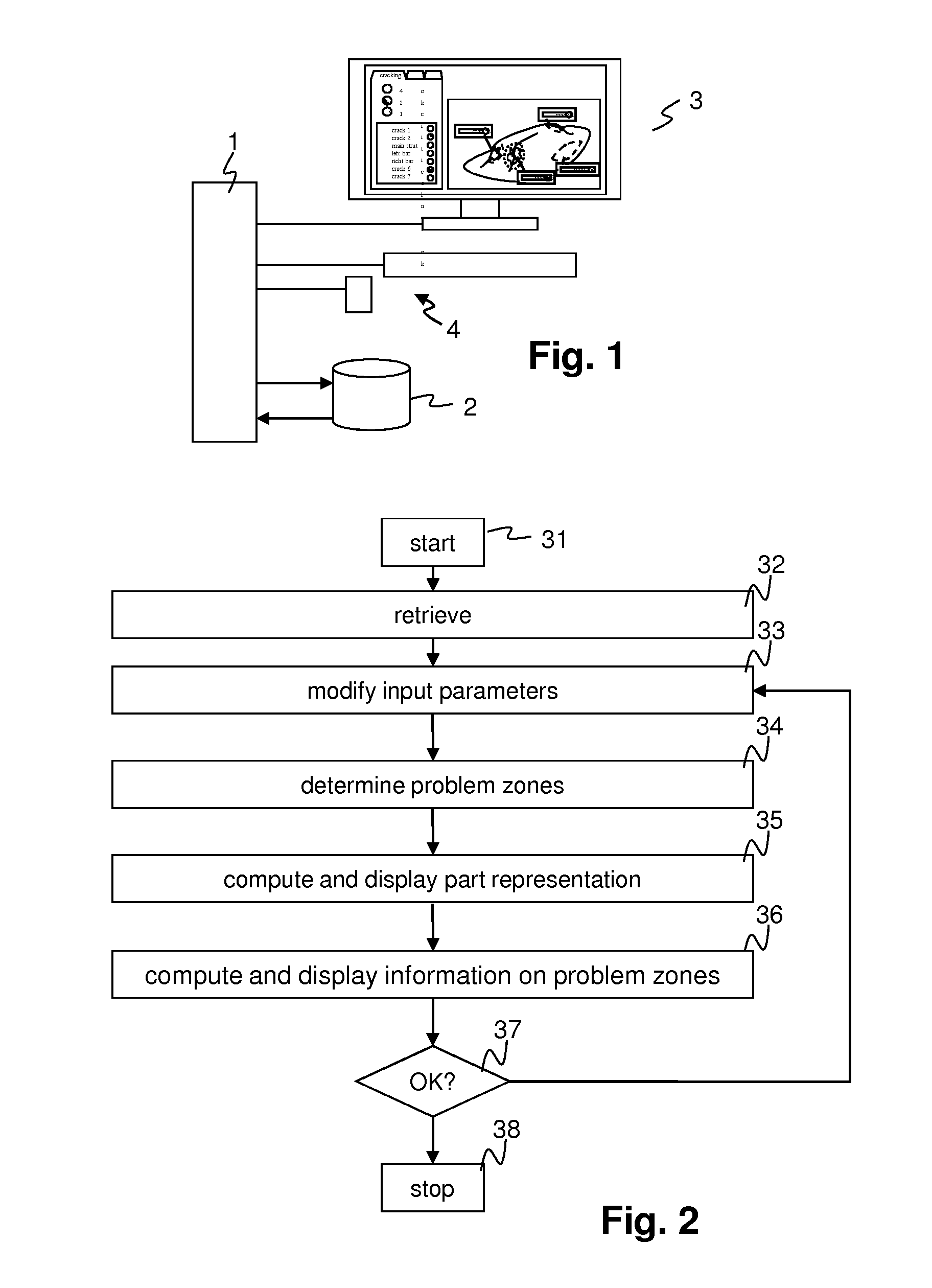
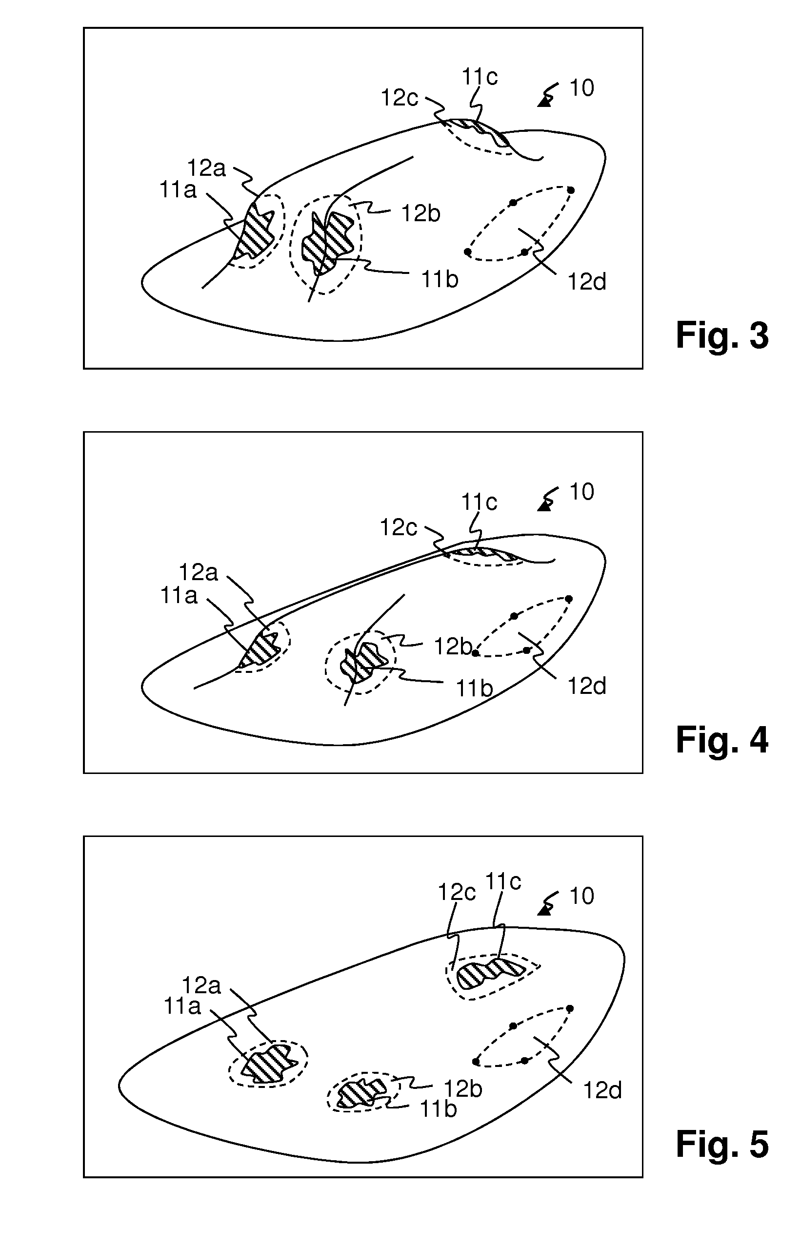
In a method for designing a formed sheet-metal part performed by a processor of a computing system, by means of:a numerical model of a geometry of the part,a numerical simulation of a forming process, andlocal property variables associated with points of the part and computed from results of the numerical simulation,a method for managing problem zones of the formed sheet-metal part comprises the steps of:determining problem zones of the sheet-metal part based on the results of the numerical simulation;determining a visual representation of the sheet-metal part, and displaying this visual representation on a display operatively coupled to the processor; indicating the location of the problem zones on the sheet-metal part; anddisplaying on the display device information associated with the at least one problem zone whose location is indicated.

Description

CROSS-REFERENCE TO RELATED APPLICATIONS[0001]U.S. patent application Ser. No. 12 / 948,531, entitled “Method and System for Designing a Formed Sheet-Metal Part”, and U.S. patent application Ser. No. 12 / 948,555, entitled “Method and System for Processing and Displaying Sheet-Metal-Forming Simulation Parameters”, each having at least one common inventor with this patent application, and being commonly owned with this patent application, were filed concurrently with this patent application, and accordingly, are incorporated by reference herein for all purposes.BACKGROUND[0002]Formed metal parts and in particular formed sheet-metal parts are manufactured in multi-component forming presses by deep drawing, restriking, folding, trimming, etc., involving different forming tools.[0003]For the configuration of metal-forming tools (for example, punches, dies, and blank holders), as well as for the configuration of metal-forming processes (for example, tool forces, draw beads, lubrication, shape...

Claims


Application Information

Patent Timeline
Patent Type & Authority Applications(United States)
IPC IPC(8): G06F17/50
CPCB21D22/20G06F17/50G06F2217/42G06F2217/12G06F2217/16G06F17/5009G06F2113/24G06F2119/18G06F2111/10G06F30/00G06F30/20Y02P90/02
Inventor KUBLI, WALDEMARKRAINER, ANDREAS
Owner NETABTAL MASCHEN
Learn More