Balanced globe valve

a globe valve and plug valve technology, applied in the direction of mechanical equipment, pressure relieving devices on sealing faces, transportation and packaging, etc., can solve the problems of large number, negative affecting system stability, and increased cost, and achieve the effect of enhancing performance and reducing cos

Inactive Publication Date: 2006-03-28
SCHNEIDER ELECTRIC BUILDINGS AMERICAS INC
View PDF3 Cites 11 Cited by
  • Summary
  • Abstract
  • Description
  • Claims
  • Application Information

AI Technical Summary

Benefits of technology

[0012]In view of the above, the present invention provides a new and improved balanced plug valve. More particularly, the present invention provides a new and improved balanced plug valve. More particularly, the present invention provides a new and improved balanced plug valve having an internal contour, the shape of which controls the modulated flow rate through the improved plug valve. Still more particularly, the present invention is directed to an improved balanced plug valve having a reduced cost and enhanced performance over previous valves by including a new plug / seat configuration.
[0013]The internal contour of the present invention provides a far more streamlined flow path allowing higher flow ratings and reduced manufacturing cost. Further, increased control and predictability of flow rates may be achieved through the present invention.
[0014]In another aspect of the present invention, the balanced plug valve of the present invention provides a metal displacement method of seat ring retention eliminates or substantially reduces the possibility of seat blow out. This is accomplished in one embodiment of the present invention with positive containment method that also may have applicability to unbalanced valves.
[0016]In addition to fully balanced operation, the sealing end configuration of the balanced plug provides for ANSI 4 or bubble tight sealing during normal operation. Further, this configuration provides an ANSI 3 metal-to-metal seal in the event of O-ring failure of the valve seat. This end configuration also provides a metal stop to prevent O-ring over compression during normal operation, thereby enhancing seal life.
[0017]While it is common to use continuous sliding seals for pistons having the continuous seals installed in grooves, the rigidity of the elastic cross-section prevents effective use of outside diameter contact due to the high friction from the compression of the cross-section. In such arrangements, radial stretch is required to control the sliding friction. However, the stretch factor varies greatly with temperature, especially with non-elastomers such as PTFE (Teflon®) in accordance with an aspect of the present invention PTFE tubing is cut to the proper length and installed with the ends butted together against each other in the groove. The squeeze of the tubing is used for proper sealing and sliding forces. This allows ease of installation, and removes the requirement of specific sealed diameters for specific sized valves. Further, sensitivity to temperature variation is significantly reduced.

Problems solved by technology

However, in such a valve, the differential pressure from the upstream side to the downstream side multiplied by the area of the obstruction separating each side results in a substantial number.
With greater actuator force requirements, costs escalate.
Further, control system dead band becomes larger, which negatively affects system stability.
When the plug is lowered from the upstream side, typically the result is that the plug slams shut against a valve seat due to upstream pressure and inertia forces pushing the plug toward the hole.
This slamming causes hammering which creates noise and valve damage.
Again, with greater actuator force requirements, costs escalate.
These valves are relatively larger and more expensive than the standard gate and plug valves.
Further, it is often difficult to ensure proper mechanical closure of both seats.
These valves are complex, and again more expensive to manufacture.
These include the fact that they have poor capability for flow modulation or for tight shut-offs.
As a result, there is a pressure differential across the plug, resulting in unbalanced forces.

Method used


Image

  • Balanced globe valve
  • Balanced globe valve
  • Balanced globe valve

Examples


Embodiment Construction

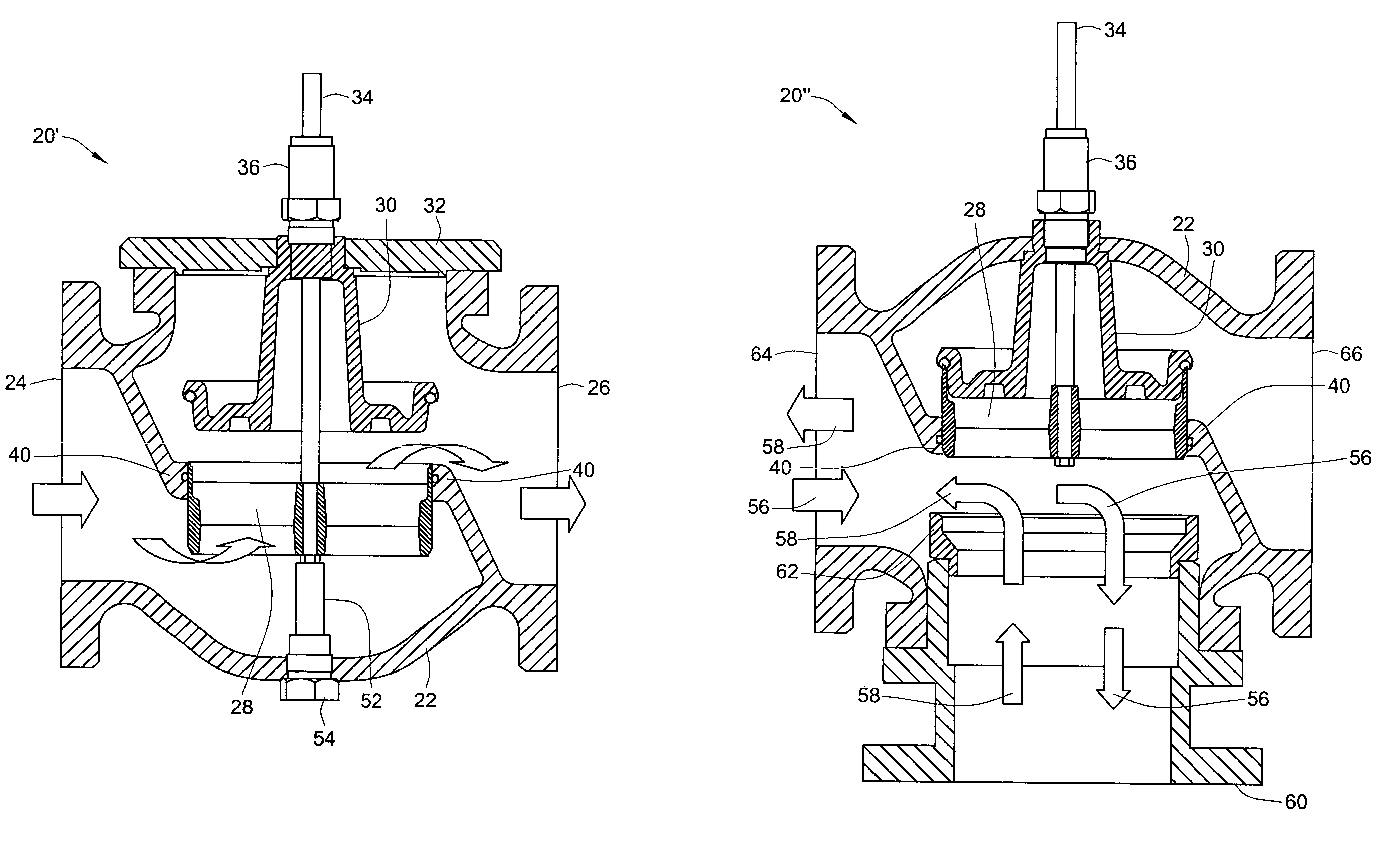
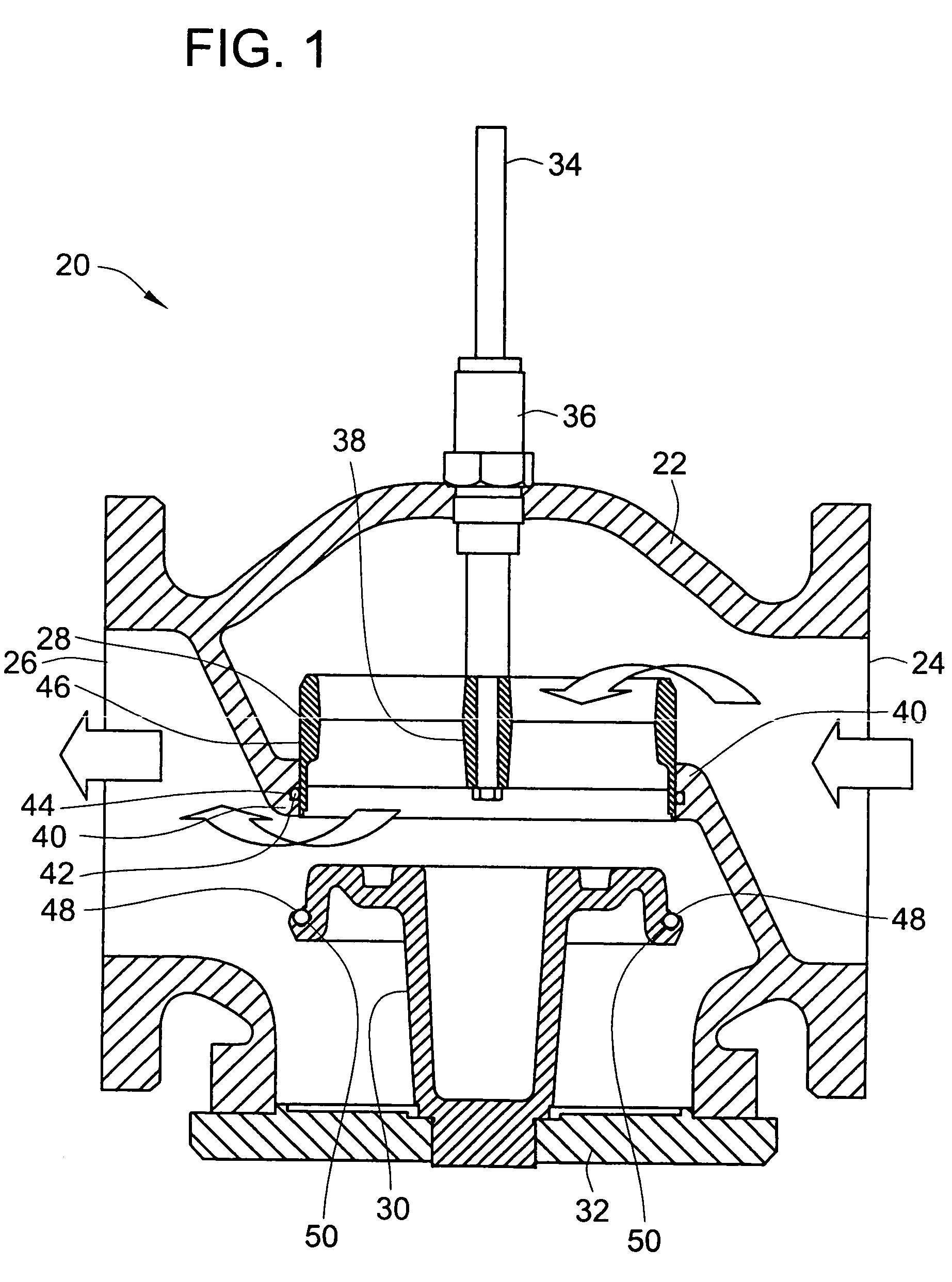
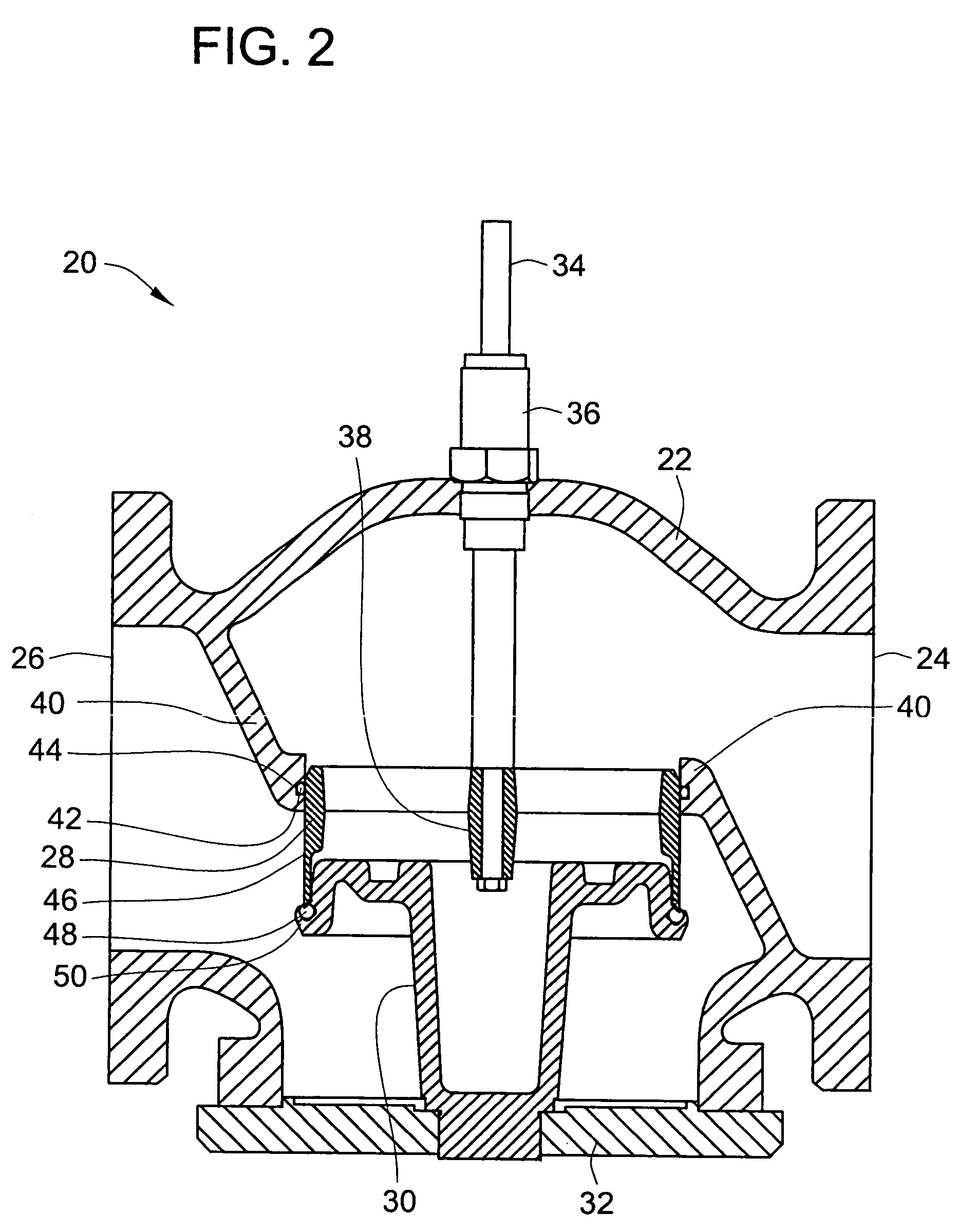
[0037]Turning now to the drawings, there is illustrated in FIG. 1 a partial cross-sectional view of a normally open fully balanced globe valve 20 constructed in accordance with the teachings of the present invention. This valve 20 includes a valve body 22 having an inlet coupling 24 and an outlet coupling 26. Regulation of the flow of fluid from the inlet 24 to the outlet 26 is accomplished through the cooperation of the balanced plug 28 and the contoured seat 30 as will be described more fully below. In this embodiment of the present invention, the contoured seat 30 is held in position within the valve body 22 by bonnet 32 that is fixably attached to the valve body 22. The relative positioning of the balanced plug 28 in relation to the contoured seat 30 is accomplished by moving valve stem 34 linearly into or out of the valve body 22 slidably through packing 36. While not illustrated in this FIG. 1, the linear movement of valve stem 34 is typically accomplished through the provisio...


PUM


Abstract

An essentially fully balanced plug valve is presented in which the flow control contour is interior to the moving member. The sealing edge of the moving member is at the exterior surface relative to the interior contour. This sealing edge is formed by use of matching angles on the interior of the moving member and the exterior of the stationary member. As a result, operation of the plug is fully balanced with the internal fluid pressure of the liquid therein. The sealing surface of the stationary member is positively retained therein to prevent blowout of the sealing surface. Should failure of the sealing surface occur, a secondary metal-to-metal seal will provide fluid containment albeit possibly at a reduced containment level.

Description

FIELD OF THE INVENTION[0001]The present invention relates generally to balanced plug valves, and more particularly to fully balanced plug valves having an internal seat contour governing flow rate modulation therethrough.BACKGROUND OF THE INVENTION[0002]Control systems and manual applications utilize various types of valves to turn fluid flows on and off, and also to modulate the rate of fluid flow through the valve. Fluid flow through a valve results from pressure differentials between upstream sources and downstream destinations. Fluid flow is a function of pressure differentials and conduit resistance. Control is generally achieved by varying the resistance to flow by varying the available flow area between zero and a maximum. A valve is the conventional method of varying area.[0003]Sliding gate valves present one method of varying flow area. However, in such a valve, the differential pressure from the upstream side to the downstream side multiplied by the area of the obstruction...

Claims


Application Information

Patent Timeline
Patent Type & Authority Patents(United States)
IPC IPC(8): F16K3/26F16K11/20F16K39/02
CPCF16K39/022F16K11/202Y10T137/86799Y10T137/86879
Inventor ERICKSON, IRVING C.GE, HONGMINGDICKINSON, BONNIE
Owner SCHNEIDER ELECTRIC BUILDINGS AMERICAS INC
Why Eureka
Try Eureka