Component of an EUV or UV lithography apparatus and method for producing it
- Summary
- Abstract
- Description
- Claims
- Application Information
AI Technical Summary
Benefits of technology
Problems solved by technology
Method used
Image
Examples
Embodiment Construction
is provided below. The description is provided by way of non-limiting examples, to be read with reference to the attached drawings in which:
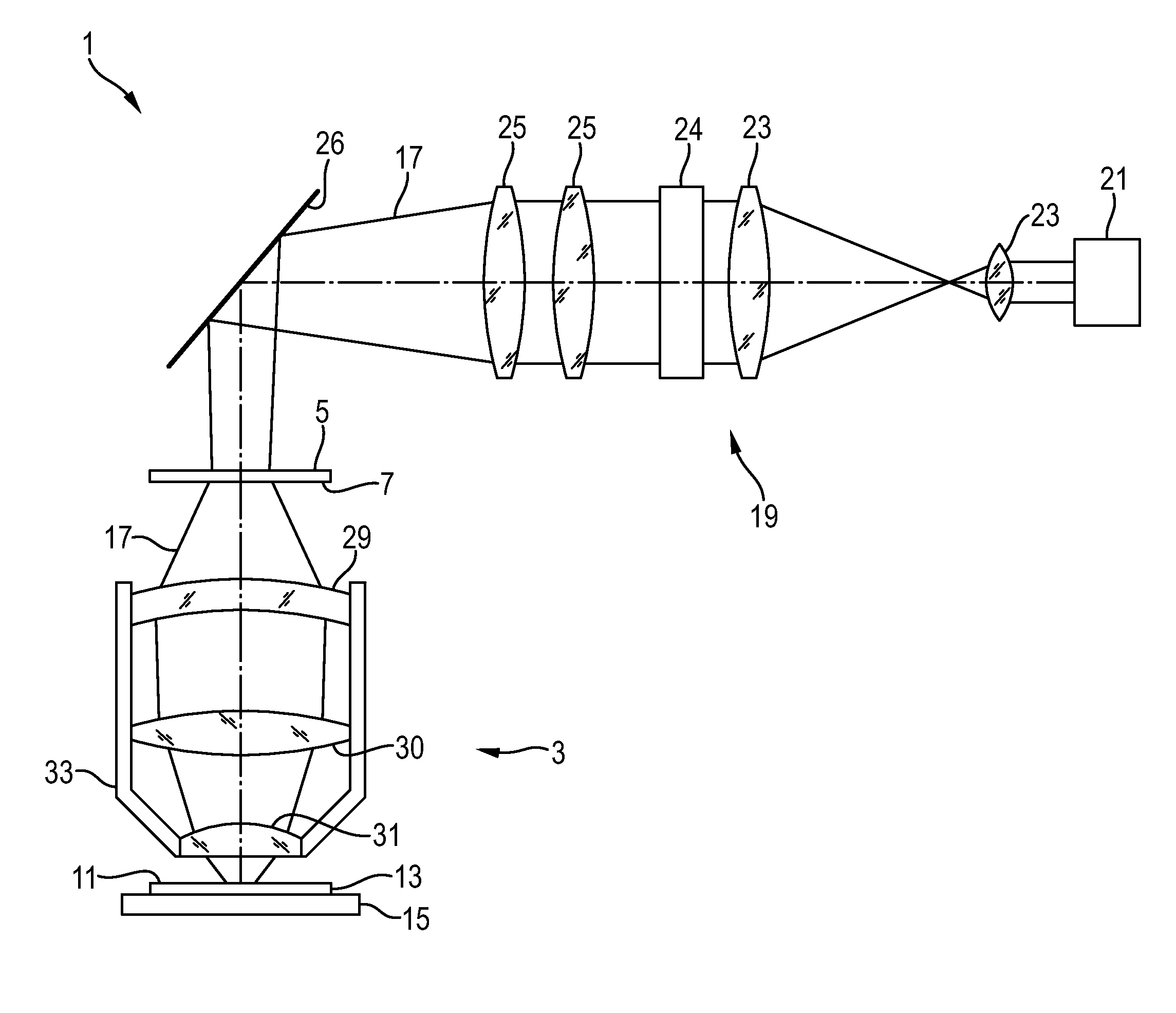
[0017]FIG. 1 illustrates schematically an embodiment of a UV lithography apparatus;
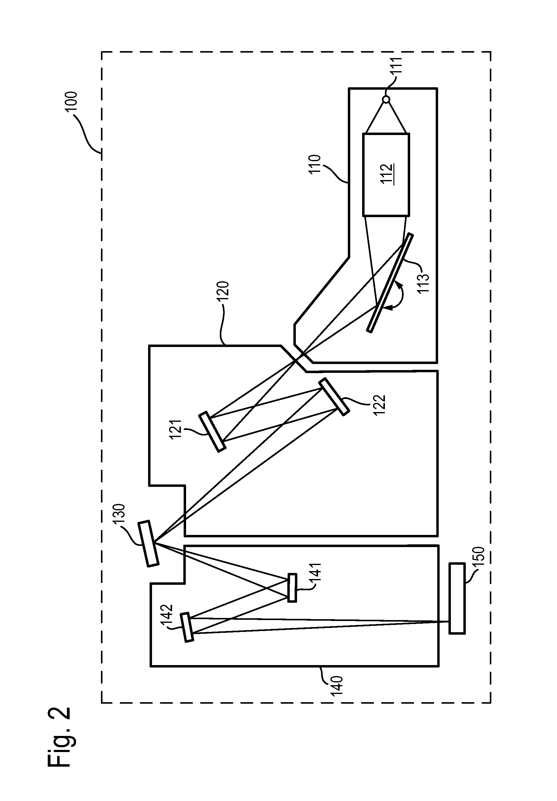
[0018]FIG. 2 illustrates schematically an embodiment of an EUV lithography apparatus;
[0019]FIGS. 3a, b illustrate schematically the bonding of a mirror or lens in a mounting;
[0020]FIG. 4 illustrates schematically an embodiment of a component of adhesively bonded parts with protective layer;
[0021]FIG. 5 illustrates schematically a scale adhesively bonded to a mounting with protective layer;
[0022]FIG. 6 illustrates schematically a scale adhesively bonded to a mounting without protective layer;
[0023]FIG. 7 illustrates the impact of a protective layer on an adhesively bonded EUV mirror; and
[0024]FIG. 8 illustrates the impact of a protective layer on an adhesively bonded UV mirror.
DETAILED DESCRIPTION
[0025]FIG. 1 shows schematically a UV lithography apparatus 1. The UV...
PUM
| Property | Measurement | Unit |
|---|---|---|
| Pressure | aaaaa | aaaaa |
| Wavelength | aaaaa | aaaaa |
Abstract
Description
Claims
Application Information
 - R&D
- Intellectual Property
- Life Sciences
- Materials
- Tech Scout
- Unparalleled Data Quality
- Higher Quality Content
- 60% Fewer Hallucinations
Browse by: Latest US Patents, China's latest patents, Technical Efficacy Thesaurus, Application Domain, Technology Topic, Popular Technical Reports.
© 2025 PatSnap. All rights reserved.Legal|Privacy policy|Modern Slavery Act Transparency Statement|Sitemap|About US| Contact US: help@patsnap.com


