
Methods and devices for restricting flexion and extension of a spinal segment

a technology of spinal segment and flexion, applied in the field of medical methods and devices, can solve problems such as suffering from one or more disadvantages

Inactive Publication Date: 2012-05-03
SIMPIRICA SPINE
View PDF3 Cites 20 Cited by
  • Summary
  • Abstract
  • Description
  • Claims
  • Application Information

AI Technical Summary

Benefits of technology

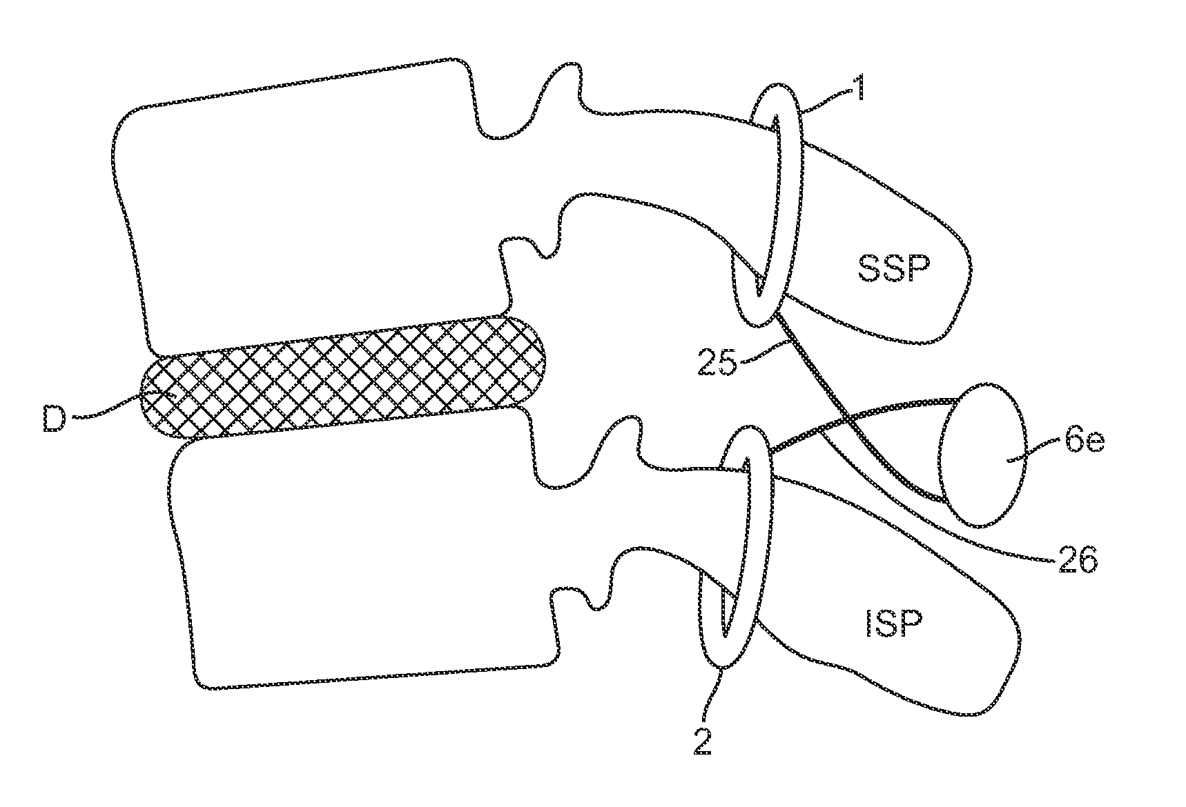
[0021]The straps on the inside of the interspinous space prevent the spinous processes from approximating. The straps could be constructed out of any material, including woven or unwoven fabric, that is substantially inextensible. Suitable materials include, but are not limited to, polyester, PET, UHMWPE, polyethylene or PEEK, for example. They could take the form of a leash, harness, lead, braid, plait, cord, belt, weave, strip, tie or band, for example. This provides advantages over a solid block, cushion or spacer implanted between the spinous processes because the straps: 1) increase flexibility; 2) minimize risk of damage to spinous processes by conforming to the bone surface; 3) cannot be easily dislodged; 4) are compatible with a variety of compliance members allowing for modular elasticity or resistance to extension; 5) deploy with less tissue removal and disruption than would be required to place a solid interspinous element between the same pair of spinous processes; 6) enable tunable adjustment of extension restriction to the needs of the patient; and 7) in combination with compliance elements, minimize peak impact loads on the spinous processes.
[0023]In a second aspect of the present invention, a device for controlling the movement of a spinal segment comprises a first strap having a first end and a second end, wherein the first strap captures a superior spinous process. A second strap has first and second ends, and the second strap captures an inferior spinous process. The first and second straps are substantially inextensible. A first compliance member has a first end connected to at least one of the first and second ends of the first strap and a second end (opposite the first end) connected to at least one of the first and second ends of the second strap. The construct of the first compliance member and straps provides resistance to extension and flexion of the spinal segment.
[0035]Another aspect of the present invention includes a device for controlling extension of a spinal segment. The device comprises a constraint coupled to a superior spinous process and an inferior spinous process. The constraint includes a first strap coupled to the inferior surface of the superior spinous process and a second strap coupled to the superior surface of the inferior spinous process. Each strap has two ends. A first compliance member has a first end and a second end opposite the first end. The first end of the first compliance member is connected to the first end of the first strap and the second end of the first compliance member is connected to the first end of the second strap. A second compliance member has a first end and a second end opposite the first end. The second compliance member is located across the midline of the spinal segment. The second compliance member has a first end and a second end opposite the first end. The first end of the second compliance member is connected to the second end of the first strap and the second end of the second compliance member is connected to the second end of the second strap. The construct of the compliance members and straps provides a force resistant to extension of the spinal segment. Changing the length of the substantially inextensible straps adjusts the resistance to extension.

Problems solved by technology

However, each of these references suffers from one or more of the disadvantages previously described.

Method used


Image

  • Methods and devices for restricting flexion and extension of a spinal segment
  • Methods and devices for restricting flexion and extension of a spinal segment
  • Methods and devices for restricting flexion and extension of a spinal segment

Examples


Embodiment Construction

[0051]The following exemplary embodiments of methods and devices will be described in the context of applying a constraint around the spinous processes to restrict flexion and extension of a spinal segment. This is intended to be for illustrative purposes only and one of ordinary skill in the art will recognize that the methods and devices disclosed herein may be used in a number of other applications and therefore are not limited to spinal surgery. The features and advantages will become apparent upon reading the following detailed description and referring to the accompanying drawings in which like numbers refer to like parts throughout.

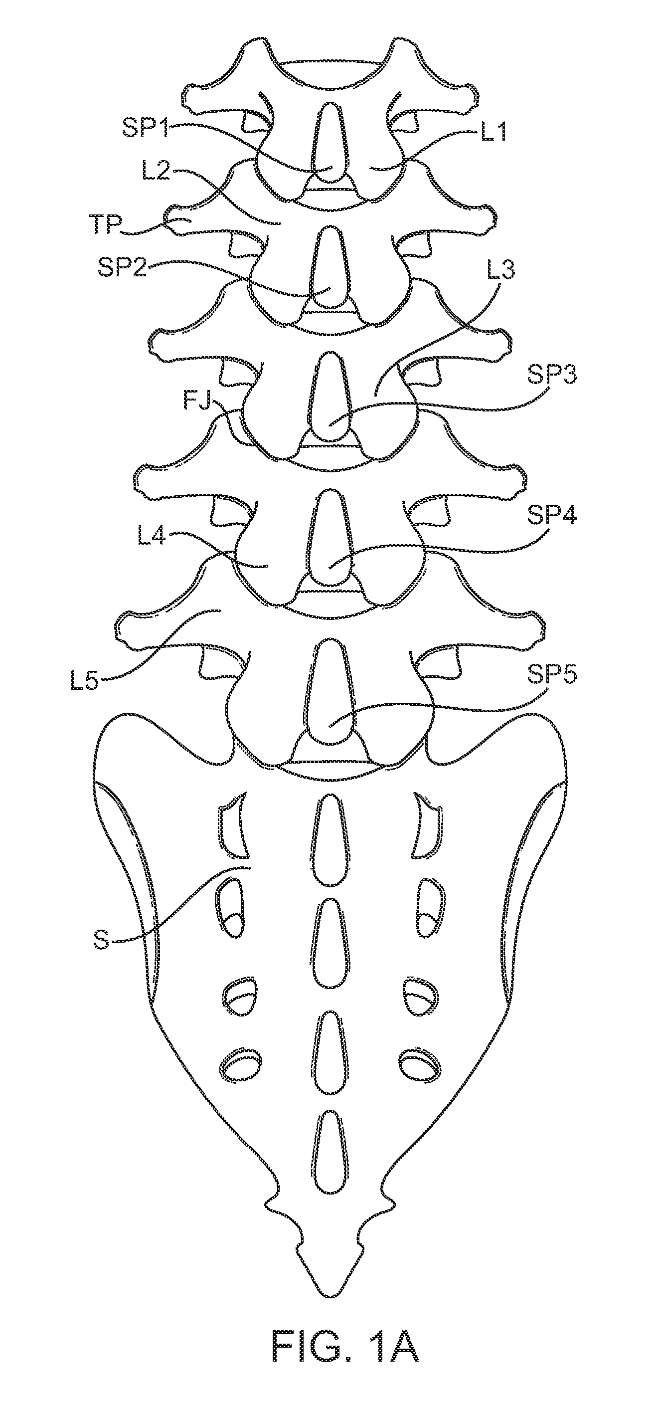
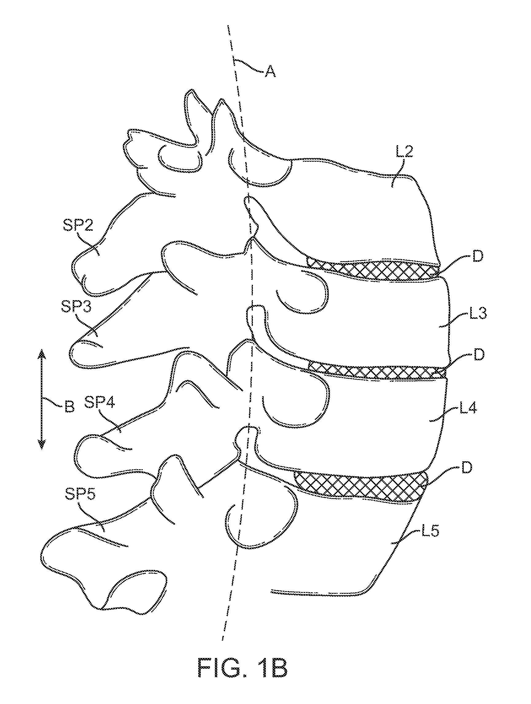
[0052]FIG. 1A is a schematic diagram illustrating the lumbar region of the spine including the spinous processes (SP), facet joints (FJ), lamina (L), transverse processes (TP), and sacrum (S). FIG. 1B is a schematic illustration showing a portion of the lumbar region of the spine taken along a sagittal plane and is useful for defining the terms “ne...


PUM


Abstract

Methods and devices for restricting movement of a spinal segment by providing an adjustable constraining device that includes a tether and a compliance member coupled together. The tether is coupled to a superior spinous process and an inferior spinous process or a sacrum so that the construct of the compliance member and tethers provides a force resistant to flexion and a force resistant to extension of a spinal segment. In some embodiments, the construct of the compliance member and tethers may provide only a force resistant to extension.

Description

CROSS-REFERENCE TO RELATED APPLICATIONS[0001]This application is a continuation of International Patent Application No. PCT / US2009 / 065658 (Attorney Docket No. 026398-001110PC) filed Nov. 24, 2009, which claims the benefit of U.S. Provisional No. 61 / 117,428 (Attorney Docket No. 026398-001100US) filed Nov. 24, 2008, the contents of which are incorporated herein by reference.BACKGROUND OF THE INVENTION[0002]1. Field of the Invention[0003]The present invention generally relates to medical methods and devices. More particularly, the present invention relates to methods and devices used to restrict flexion and / or extension of a spinal segment. This includes but is not limited to treatment of patients having back pain, spinal abnormalities or other conditions of the spine and / or vertebral column.[0004]Spinal stability is highly dependent on the patency of attached soft tissue such as ligaments, spinal load and posture as well as task requirements. In particular, the ligaments and disc play...

Claims


Application Information

Patent Timeline
IPC IPC(8): A61B17/70A61B17/88
CPCA61B17/7053A61B17/7067A61B17/7062
Inventor CAHILL, COLINKOTHARI, MANISHALAMIN, TODDFIELDING, LOUIS
Owner SIMPIRICA SPINE
Learn More