
Perforated Ticket Dispensing Machine

a ticket dispenser and perforation technology, applied in the field of ticket dispensers, can solve the problems of controllers not always sensing errors, improperly cutting tickets, and inability to detect sensors, etc., and achieve the effects of easy removal, high compliance, and light weigh

Active Publication Date: 2012-04-12
IGT GLOBAL SOLUTIONS CORP
View PDF18 Cites 8 Cited by
  • Summary
  • Abstract
  • Description
  • Claims
  • Application Information

AI Technical Summary

Benefits of technology

[0013]The exit sensor incorporates a mechanical flag switch that is activated by the ticket media that needs to be detected. In one embodiment of the present invention, the flag switch covers the entire width of the machine. To sense the position of the flag, a Hall effect sensor can be used. The Hall effect sensor is activated by a magnetic field. The magnetic system of the exit flag includes a small magnet attached to the flag, a magnetic conductor attached to the edge of the ticket machine frame, and a Hall effect sensor attached to the ticket machine frame. The magnetic conductor helps with providing a definitive tripping point for the Hall effect sensor, which operates in a binary mode, i.e., with one output that indicates there is a magnetic connection and another output that indicates the lack thereof.
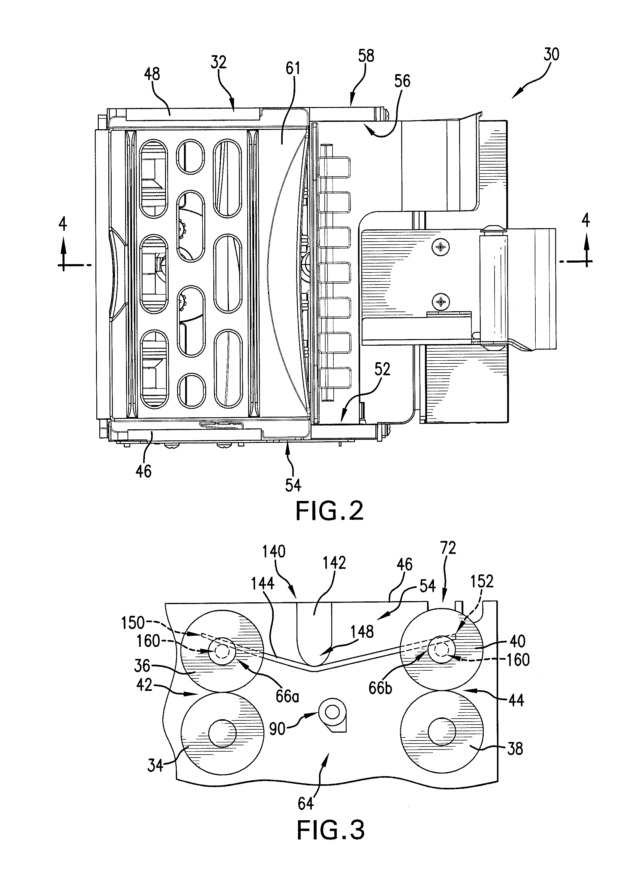
[0015]The present invention further provides an exit sensor flag that can reach between the exit drive and exit idler roller (inside of the frame toward the exit roller nip point). As such, it is capable of sensing tickets that are curled much more effectively. The closer the ticket can be sensed to the nip, the less it will be affected by curling. Also because there is no obstruction under the roller, the ticket can not hang up and is free to fall.
[0017]The present invention further provides the ability to maintain high compliance regardless of the thickness of the ticket substrate being processed. The present invention accomplishes this, in part, through the use of a leaf spring arrangement that accommodates media of different sizes and thicknesses. A leaf spring is in contact with both the feed and the exit idler roller shaft. The fixed point of the leaf spring can be offset to give the feed roller more downward force. This is done by securing a spring guide to the inside of the frame at a position closer to the feed rollers than the exit rollers.
[0018]In addition to the above, the frame of the present invention can be independently inserted into and retrieved out of a larger ticket dispensing machine. As a result, the removal and installation of each bin is done separately, without the use of tools and without any secondary power cables. The single bin burster is easy to remove, and is relatively light weight such that it can be serviced and inspected quickly. Further, a moving wall can be secured to the larger ticket dispensing machine such that, when a ticket exits any ticket burster within the dispensing machine, it will be guided by the moving wall downwardly into the ticket bin.
[0019]The present invention further provides a ticket guide attached to the outside of the frame on the input slot side. The ticket guide is adapted for sliding movement along a horizontal plane and biased in the shut position such that tickets of variable widths can be securely guided with adequate pressure on both sides as they are processed through the machine. Tickets of varying widths can thus be processed with the ticket guide opening as much as necessary to accommodate the width of the ticket. This assists in maintaining proper ticket alignment during processing, which helps eliminate improper cuts and machine shut down.

Problems solved by technology

Further, if a die cut (e.g., not rectangular-shaped) ticket is used, then the sensor will not always sense the presence of a ticket and the controller will sense an error.
Ticket processing errors can results in improperly cut tickets, ticket jams and machine shut downs while repairs take place.
All such events result in lost revenue from the machine.
In addition to the problems caused by fixed point location of optical sensor pairs, ticket burster machines suffer when attempting to process tickets of different thicknesses.
However, since tickets can range from 0.006″ to 0.012″ (and pull-tab tickets may even be up to 0.025 inches in some places), traditional systems with fixed roller distances create many problems.
A further issue with maintaining the proper nip force is created by the use of rubber material on the rollers, since this material is susceptible to wear and tear that can reduce its thickness over time, which can change the distance between rollers and thereby compromise the nip force of the rollers.
Further, current ticket bursters suffer from the inability to keep tickets of different shapes and sizes in properly aligned format as they enter the machine.
If a die-cut ticket happens to be rotated off the normal plane to the point of ticket entry in the burster machine, the cutter / burster element will not properly align with the ticket perforation, causing uneven ticket cuts and requiring that the machine be shut down.
To remove the quad burster, one is required to remove screws and lift away the four bins as an integrated assembly, which can be cumbersome.
Also, because the four bins are inseparable, the failure of one bin will result in the failure of the remaining three bins.

Method used


Image

  • Perforated Ticket Dispensing Machine
  • Perforated Ticket Dispensing Machine
  • Perforated Ticket Dispensing Machine

Examples


Embodiment Construction

[0040]The ticket burster machine of the present invention provides for controlled delivery of perforated ticket products. As shown in FIGS. 2 through 5, the ticket burster machine 30 includes a frame 32 housing a pair of feed rollers, including a feed drive roller 34 and a feed idler roller 36, as well as a pair of exit rollers, including an exit drive roller 38 and an exit idler roller 40. In one embodiment of the present invention, at least one roller on each pair of rollers is formed from aluminum and has either an aluminum oxide or silicon carbide coating. Such a coating helps resist wear and tear, and provide a high friction surface that retains proper nip force. The pair of feed rollers meet at a feed roller nip position 42 and the pair of exit rollers meet at an exit roller nip position 44.

[0041]The frame includes first 46 and second 48 side walls and can further include a back wall 50. The first side wall 46 has an inner 52 and outer 54 surface. The second side wall 48 also ...


PUM

PropertyMeasurementUnit
lengthaaaaaaaaaa
lengthaaaaaaaaaa
distancesaaaaaaaaaa

Abstract

The present invention provides an independently operable and serviceable ticket burster machine that properly handles perforated tickets of all shapes, sizes and thicknesses. The present invention includes a ticket burster element, an exit sensor with a mechanical flag switch, an inventory flag spanning the entire width of the ticket input slot and having an optical slot switch, a slidable ticket guide, one or more leaf spring arrangements and versatile and durable rollers.

Description

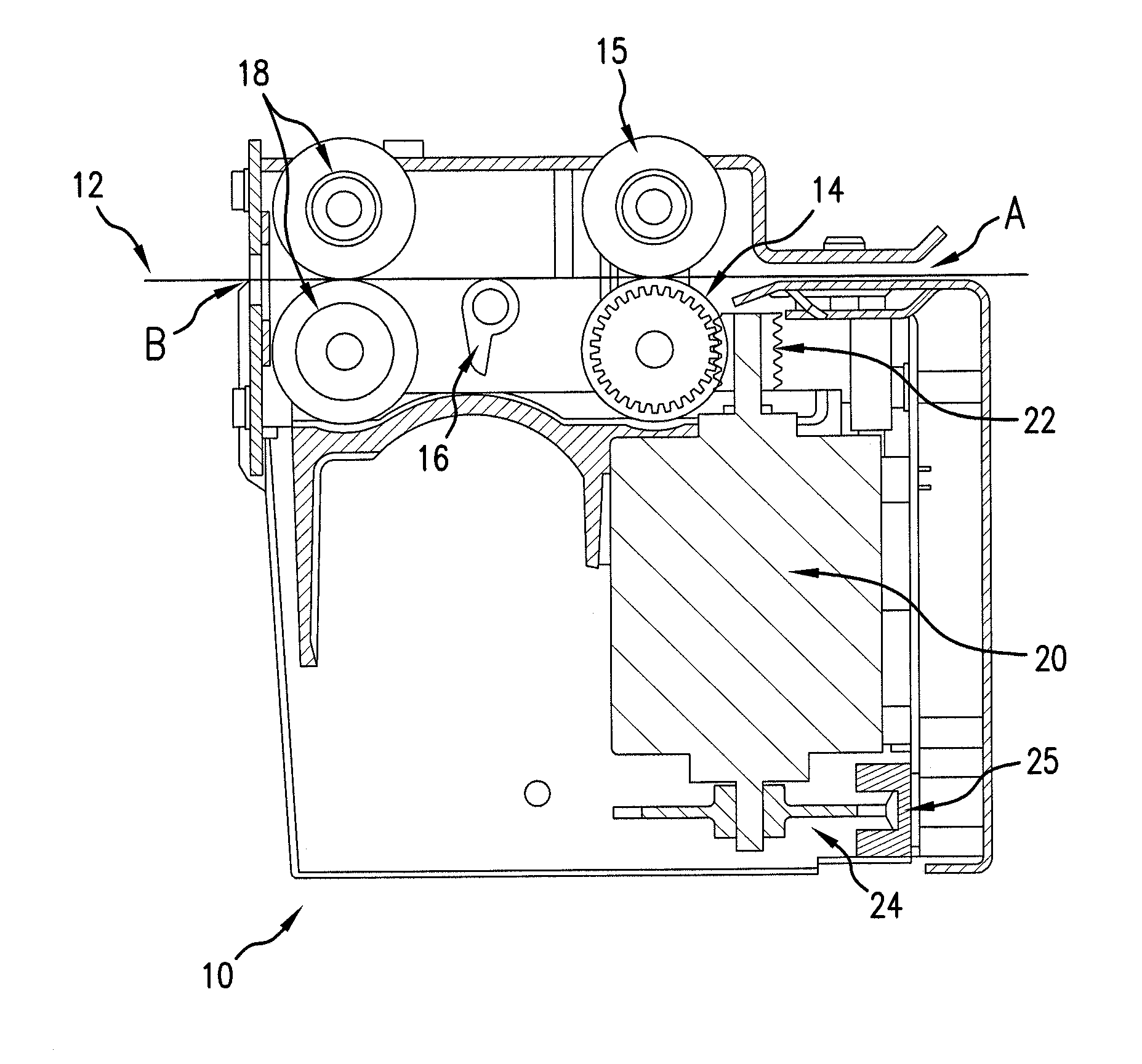
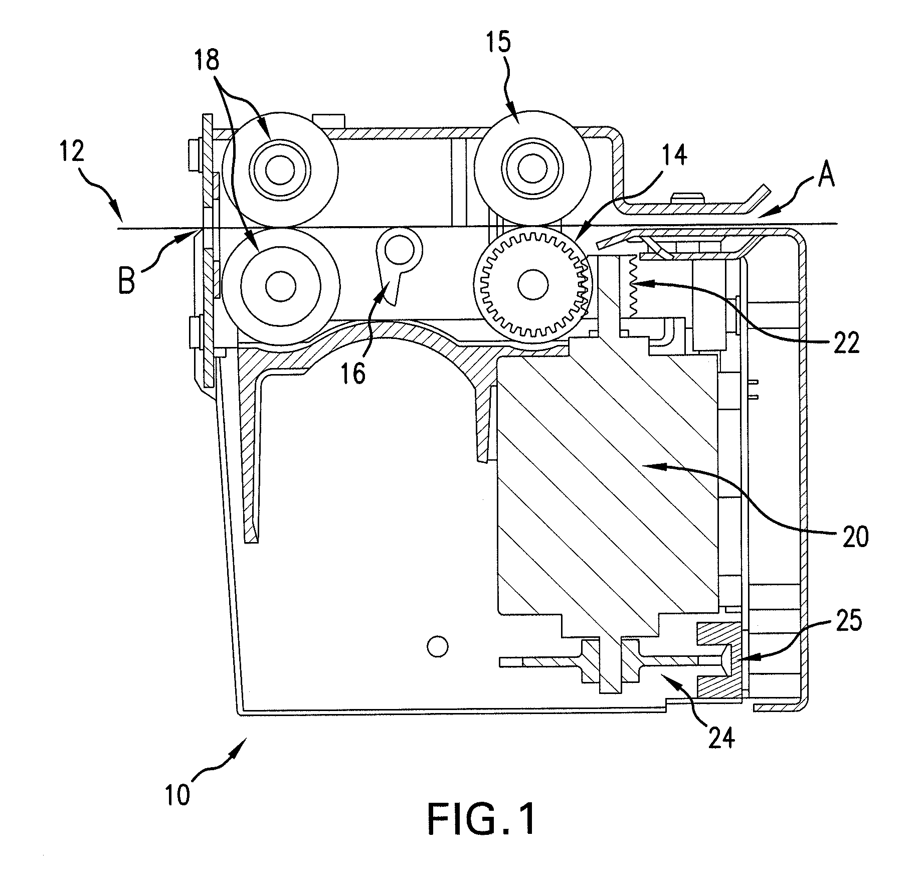
FIELD OF THE INVENTION [0001]The present invention relates to ticket dispensing machines, and more particularly to a ticket dispensing machine for handling tickets of unconventional shapes and sizes.BACKGROUND OF THE INVENTION[0002]More and more instant lottery tickets are sold in automatic vending machines. Usually, the instant tickets are printed on a long strip, which may be fan-folded, and the individual tickets are separated by perforations. The ticket width typically varies from 2 to 4 inches and the length typically varies from 2 to 12 inches. However, “die cut” tickets which have irregular shapes are becoming increasingly popular.[0003]During the ticket delivery process, the perforation must be placed very accurately under a cutting or separating system that will burst the perforation and send a single ticket to the presentation stage, such as a bin that allows a purchaser to retrieve a purchased ticket through a window, for example.[0004]FIG. 1 shows a cross section of a ty...

Claims


Application Information

Patent Timeline
Patent Type & Authority Applications(United States)
IPC IPC(8): B65D83/12B65H35/10
CPCB65H35/10B26F3/00B65H2701/1936Y10T225/371Y10T225/35Y10T83/896Y10T83/2079G07F11/68G07F11/42
Inventor BUCCI, PAUL ANTHONYBUSINGER, KURT L.
Owner IGT GLOBAL SOLUTIONS CORP
Learn More