Suction arrangement for a hermetic refrigeration compressor

a compressor and gas suction technology, applied in the direction of machines/engines, liquid fuel engines, positive displacement liquid engines, etc., can solve the problems of unusable conventional constructions, undesired leakage of refrigerant fluid in the form of gas, volume loss of said gas in the refrigeration system, etc., to facilitate heat exchange, improve thermal insulation, and dissipate heat coming

Inactive Publication Date: 2012-03-15
EMBRACO IND DE COMPRESSORES E SOLUCOES EM REFRIGERACAO LTDA
View PDF9 Cites 10 Cited by
  • Summary
  • Abstract
  • Description
  • Claims
  • Application Information

AI Technical Summary

Benefits of technology

[0018]The arrangement of the present invention also allows a better thermal insulation of the gas being drawn from the compressor environments which are at a higher temperature than that desirable for the suction.
[0019]The constructive compressor arrangement of the present invention provided with the outer cover further facilitates the heat exchange, through the head wall, of the relatively hot gas in the discharge chamber with the external environment, which acts in dissipating the heat coming from the discharge chamber.
[0020]According to another aspect of the present invention, the head provided with the outer cover allows noise attenuation, which is desirable in compressors operating with refrigerant gas CO2 used for commercial refrigeration. This construction further provides an increase of the thermal exchange of the relatively hot gas in the discharge chamber with the external environment, reducing the overheating of the inner components of the compressor (which improves its reliability) and of the gas being drawn (which improves the compressor efficiency).
[0021]In another aspect of the present invention, the oil, which by chance is carried with the gas being drawn, is drained to a lower portion of the insert provided in the head, being hermetically directed, therefrom, to the interior of the compressor shell, until reaching an oil sump defined in a lower portion of the compressor shell, having as advantage the maintenance of an oil level adequate to lubricate the relatively moving parts of the compressor.

Problems solved by technology

However, these conventional constructions are not generally used in refrigeration systems which operate with refrigerant fluid having carbon in its composition, such as CO2, since such systems present operational pressures higher than those obtained with other refrigerant fluids, requiring stronger compressors.
The systems for fixing the head to the cylinder block, by means of screws, can present, over time, undesired leak of the refrigerant fluid in the form of gas.
Since the head in these constructions is external to the contour of the shell portion, the refrigerant gas may leak to the environment in which the compressor is installed, resulting in volume loss of said gas in the refrigeration system.
Besides the possibility of gas leak, the known compressor constructions having the head external to the shell contour present an undesired noise level.

Method used


Image

  • Suction arrangement for a hermetic refrigeration compressor
  • Suction arrangement for a hermetic refrigeration compressor
  • Suction arrangement for a hermetic refrigeration compressor

Examples


Embodiment Construction

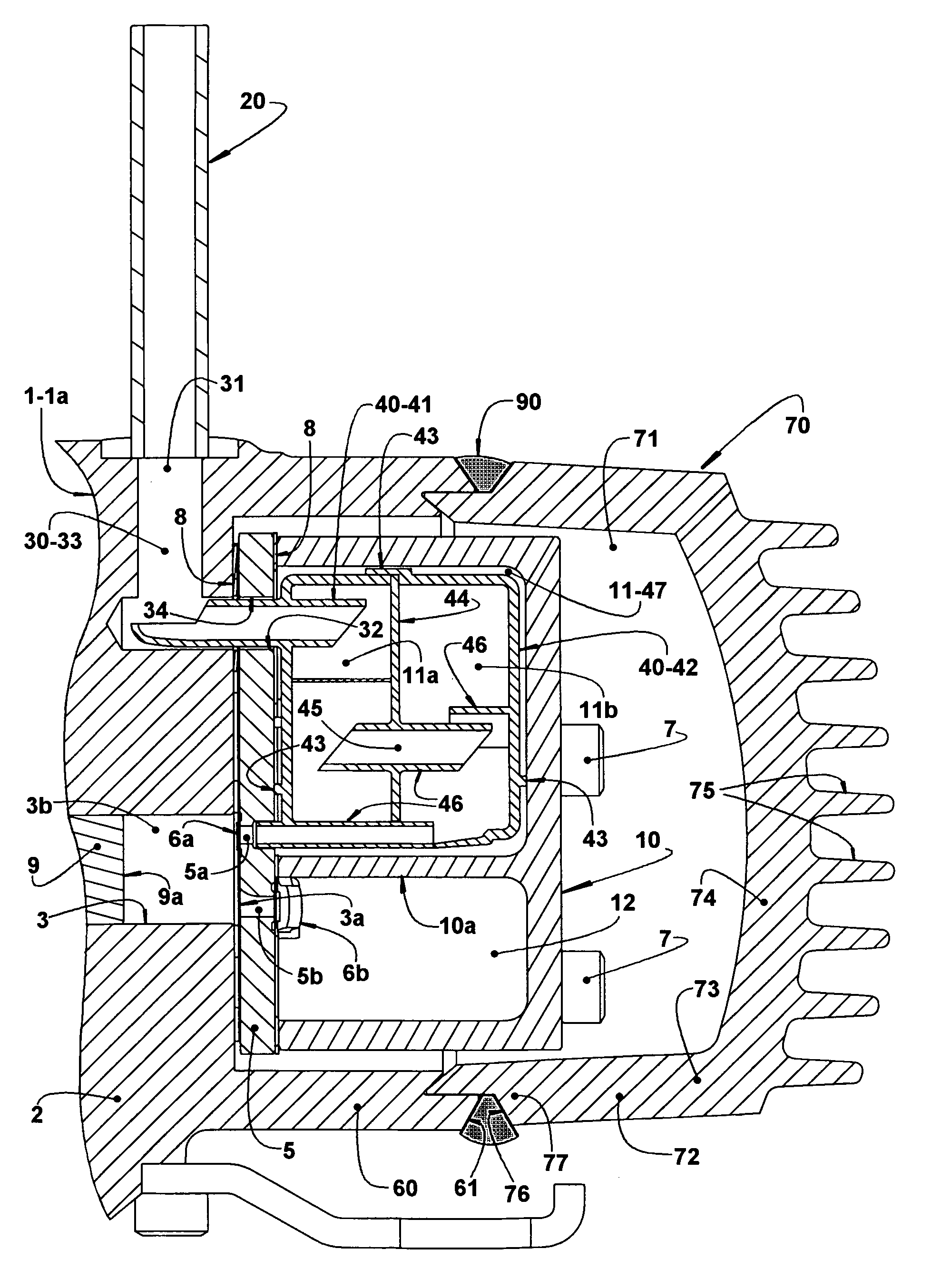
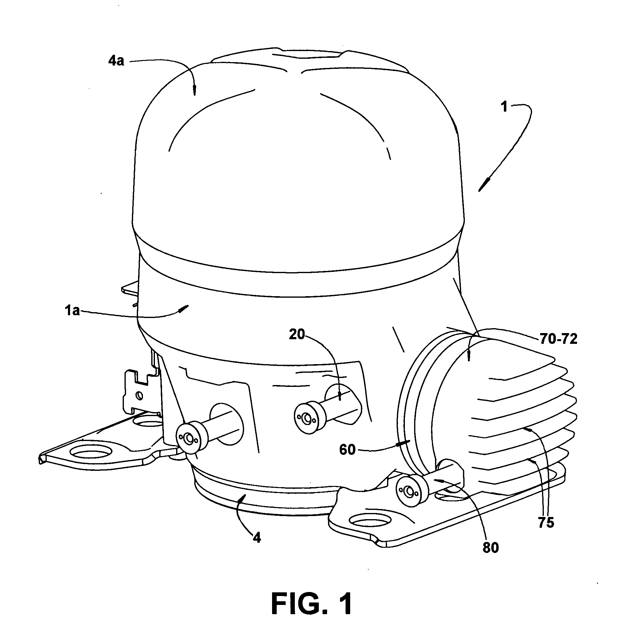
[0027]The present invention will be described for a hermetic refrigeration compressor of the type which comprises a hermetic shell 1 and a motor-compressor assembly, which includes a cylinder block 2 defining, in a single piece, a shell portion 1a of the hermetic shell 1 and a compression cylinder 3 having an end 3a, which is opened to the exterior of the hermetic shell 1.

[0028]The shell portion 1a receives and affixes at least one end cover 4 which, when positioned inferiorly to the shell portion 1a, generally internally defines an oil sump (not illustrated). The shell portion 1a and the end cover 4, when affixed to each other, define the hermetic shell 1. In the illustrated construction, the shell portion 1a receives and affixes an upper end cover 4a and a lower end cover 4.

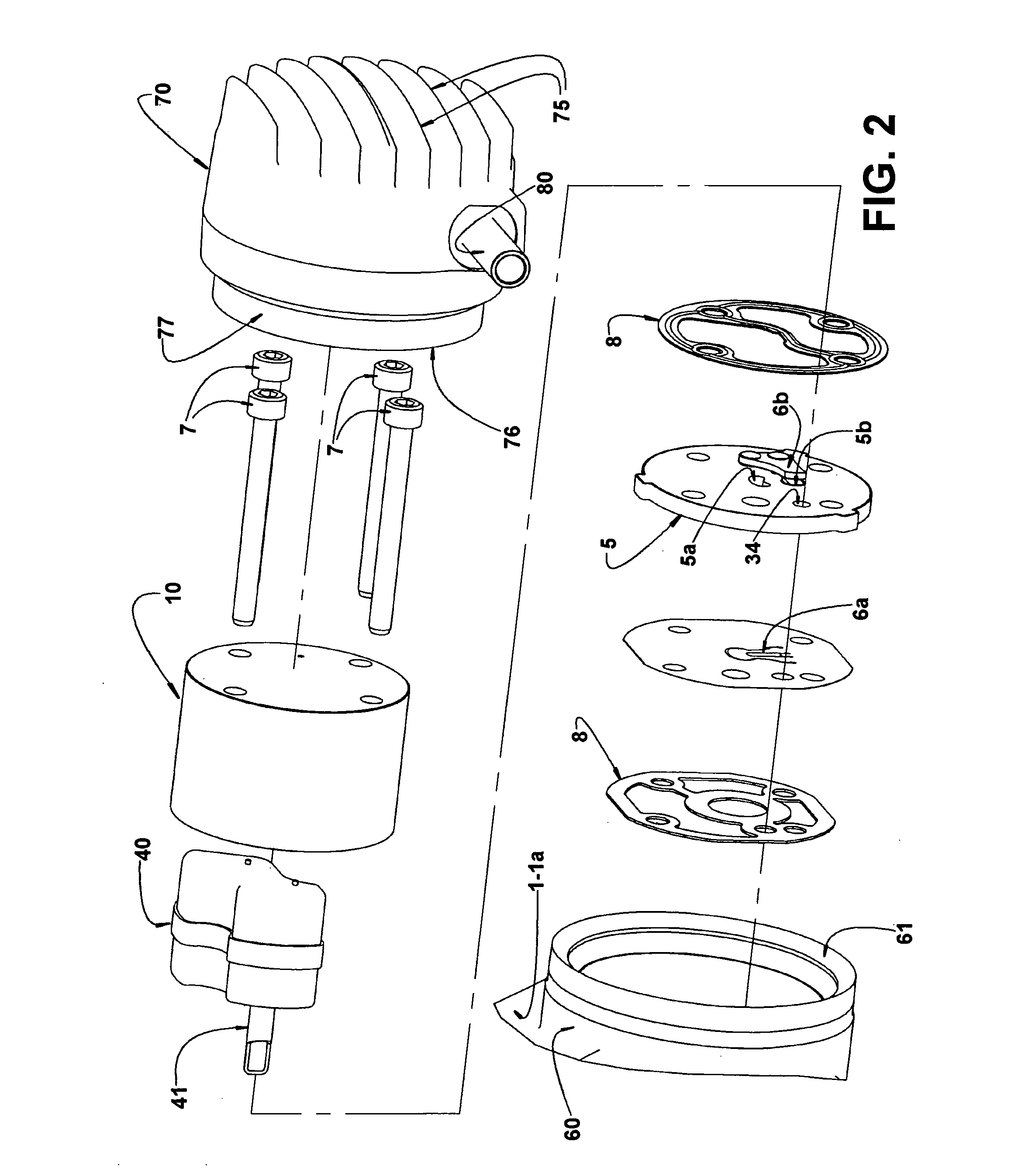
[0029]The compression cylinder 3 presents its end 3a, which is opened to the exterior of the hermetic shell 1, closed by a valve plate 5 provided with a suction orifice 5a and a discharge orifice 5b which are r...


PUM


Abstract

The suction arrangement of the present invention is for a hermetic compressor of the type which includes a hermetic shell; a cylinder block defining, in a single piece, a shell portion and a compression cylinder having an end opened to the exterior of the hermetic shell and closed by a valve plate; a head affixed to the cylinder block onto the valve plate so as to define, with the latter, at least one suction chamber receiving refrigerant gas from a gas inlet pipe external to the hermetic shell. The suction arrangement of the present invention comprises a gas inlet duct defined through the shell portion and through the valve plate and having an outer end hermetically coupled to the gas inlet pipe and an inner end opened to the suction chamber.

Description

FIELD OF THE INVENTION[0001]The present invention refers to a gas suction constructive arrangement for a hermetic refrigeration compressor of the type which comprises a cylinder block defining a shell portion which is hermetically closed, at one end, by a cover, and which carries the motor-compressor assembly of the compressor. The motor-compressor assembly presents a piston reciprocating in the interior of a cylinder defined in the cylinder block and which is closed, at one end, by a head whose interior defines a discharge chamber. This compressor construction is, for example, of the type used in refrigeration systems in which the refrigerant fluid generally contains carbon in its composition, such as CO2.BACKGROUND OF THE INVENTION[0002]The conventional reciprocating compressors generally present a hermetic shell, inside which is mounted a motor-compressor assembly in which the compression system presents a cylinder block having one end closed by a cylinder cover, affixed to the c...

Claims


Application Information

Patent Timeline
Patent Type & Authority Applications(United States)
IPC IPC(8): F04B39/12F04B53/16
CPCF04B27/1081F04B39/0061F04B39/125F04B39/12F04B53/16F04B53/007F04B39/123F04B39/122F04B53/002
Inventor MOREIRA, EMERSONFAGOTTI, FABIANWEBER, GUSTAVO CARDOSOPEREIRA, MILTON WETZELMACIEL, RICARDO ALEXANDRE
Owner EMBRACO IND DE COMPRESSORES E SOLUCOES EM REFRIGERACAO LTDA
Why Eureka
Try Eureka