Laser light source apparatus
a technology of laser light source and light source holder, which is applied in the direction of instruments, non-linear optics, optical elements, etc., can solve the problems of unacceptably increasing manufacturing costs and high adjustment mechanisms, and achieves the effect of simplifying the angular adjustment of the optical element and ensuring the mounting precision of the optical element with respect to the holder
- Summary
- Abstract
- Description
- Claims
- Application Information
AI Technical Summary
Benefits of technology
Problems solved by technology
Method used
Image
Examples
first embodiment
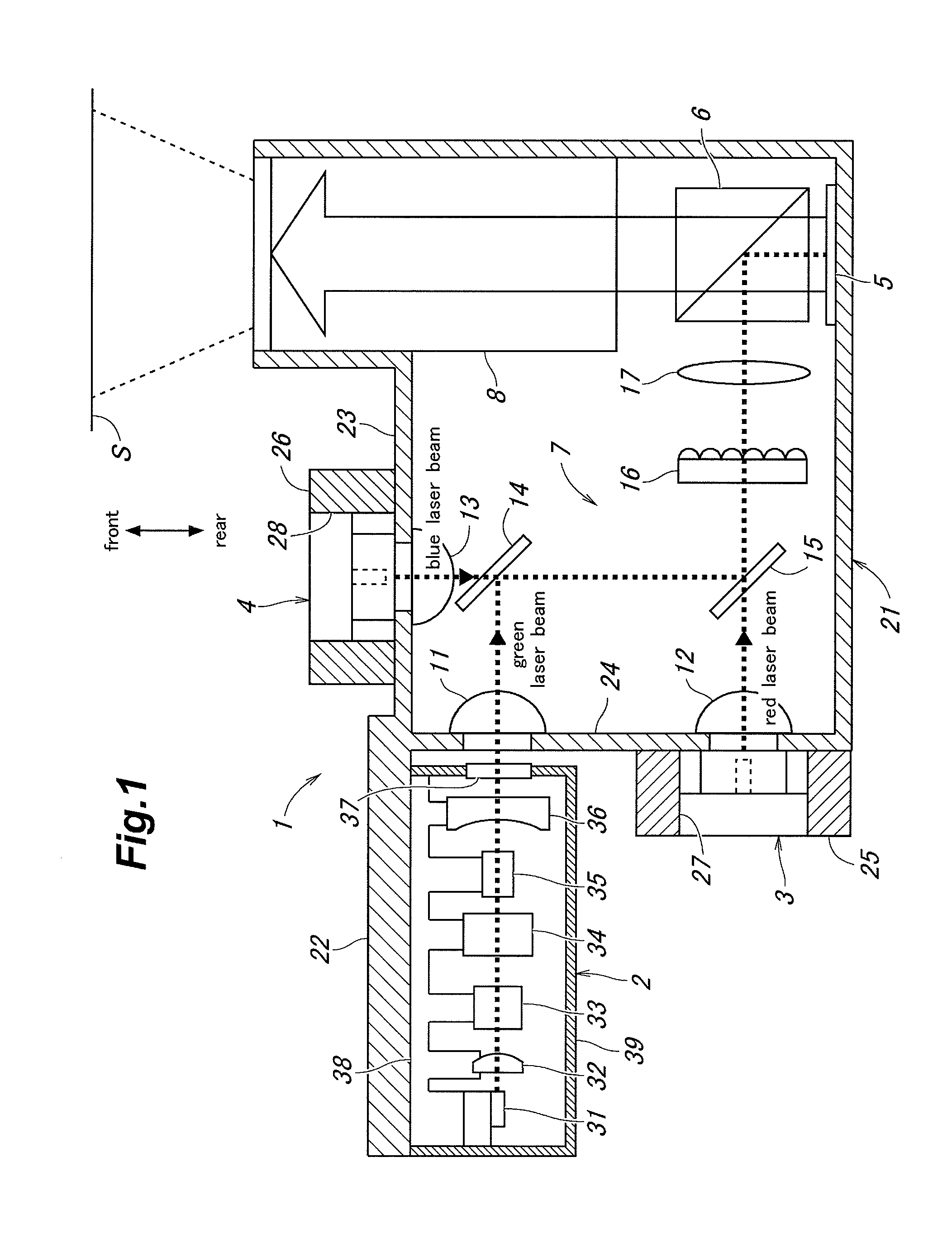
[0081]A first embodiment of the present invention is described in the following with reference to FIGS. 1 to 10.
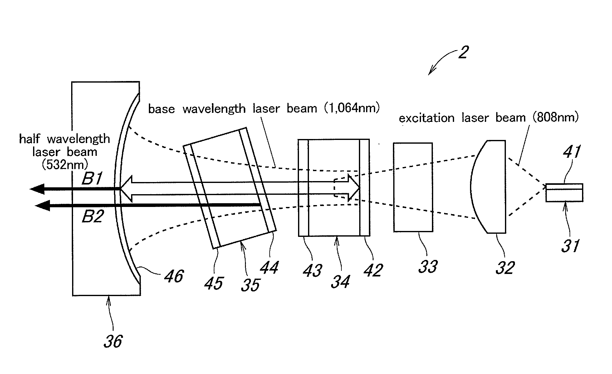
[0082]FIG. 1 is a schematic diagram showing an image display system incorporated with a green laser light source apparatus (green laser light source unit 2) embodying the present invention. The image display system 1 is configured to project a given image onto a screen S, and comprises a green laser light source unit 2 for emitting a green laser beam, a red laser light source unit 3 for emitting a red laser beam, a blue laser light source unit 4 for emitting a blue laser beam, a spatial light modulator 5 of a reflective LCD type for forming the required image by spatially modulating the laser beams from the green, red and blue laser light source units 2 to 4 according to the given video signal, a polarizing beam splitter 6 that reflects the laser beams emitted from the green, red and blue laser light source units 2 to 4 onto the spatial light modulator 5 and transmits the ...
second embodiment
[0140]A second embodiment of the present invention is described in the following with reference to FIGS. 12 to 18.
[0141]FIG. 12 is a view similar to FIG. 3 showing a green laser light source unit 2 given as a second embodiment of the present invention, and FIG. 13 is a cross sectional view of the green laser light source unit 2. In the following description, the parts corresponding to those of the previous embodiment are denoted with like numerals without repeating the description of such parts.
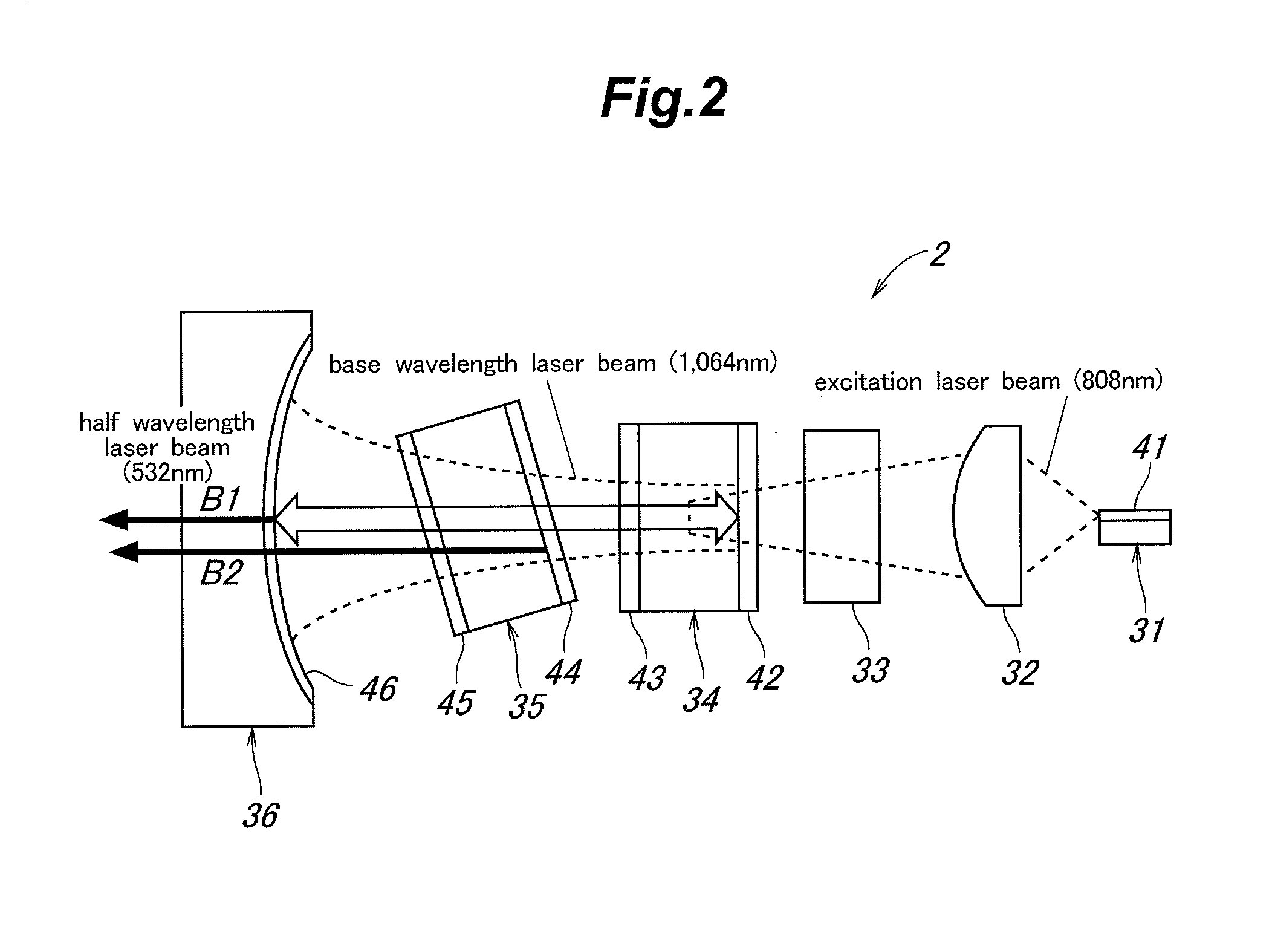
[0142]As shown in FIG. 12, a semiconductor laser 31, a FAC lens 32, a rod lens 33, a laser medium 34, a wavelength converting device 35 and a concave mirror 36 are integrally supported by a base 38 which has a bottom surface 51 extending in parallel with the optical axial line. The direction perpendicular to the bottom surface 51 of the base 38 is referred to as the vertical direction, and the direction perpendicular to both the vertical direction and the optical axial line is referred to as ...
third embodiment
[0186]A third embodiment of the present invention is described in the following with reference to FIGS. 21 to 23. The third embodiment uses a wavelength converting device 35 similar to those used in the first and second embodiments.
[0187]FIG. 21 is a schematic diagram showing the process of fabricating the wavelength converting device 35. The wavelength converting device 35 shown in FIG. 4 is fabricated by the process illustrated in FIG. 21. First of all, an electrode film is formed on the surface of a wafer 75 consisting of a ferroelectric crystal, and an electrode pattern including the periodic electrodes and opposing electrodes is formed in the electrode film by photolithography and etching. A substrate 76 is cut out from the wafer 75, and is further cut into a plurality of elongated pieces called stacks 77. By applying a voltage to the electrodes of each stack 77 to cause periodic inversion of crystal domains, a periodic poled structure can be obtained. The end surfaces 78 and 7...
PUM
| Property | Measurement | Unit |
|---|---|---|
| width | aaaaa | aaaaa |
| wavelength | aaaaa | aaaaa |
| wavelength | aaaaa | aaaaa |
Abstract
Description
Claims
Application Information
 - R&D
- Intellectual Property
- Life Sciences
- Materials
- Tech Scout
- Unparalleled Data Quality
- Higher Quality Content
- 60% Fewer Hallucinations
Browse by: Latest US Patents, China's latest patents, Technical Efficacy Thesaurus, Application Domain, Technology Topic, Popular Technical Reports.
© 2025 PatSnap. All rights reserved.Legal|Privacy policy|Modern Slavery Act Transparency Statement|Sitemap|About US| Contact US: help@patsnap.com


