
Method and Controller for Controlling a Safety-Oriented Industrial Automation Component

Active Publication Date: 2010-11-04
SIEMENS AG
View PDF6 Cites 5 Cited by
  • Summary
  • Abstract
  • Description
  • Claims
  • Application Information

AI Technical Summary

Benefits of technology

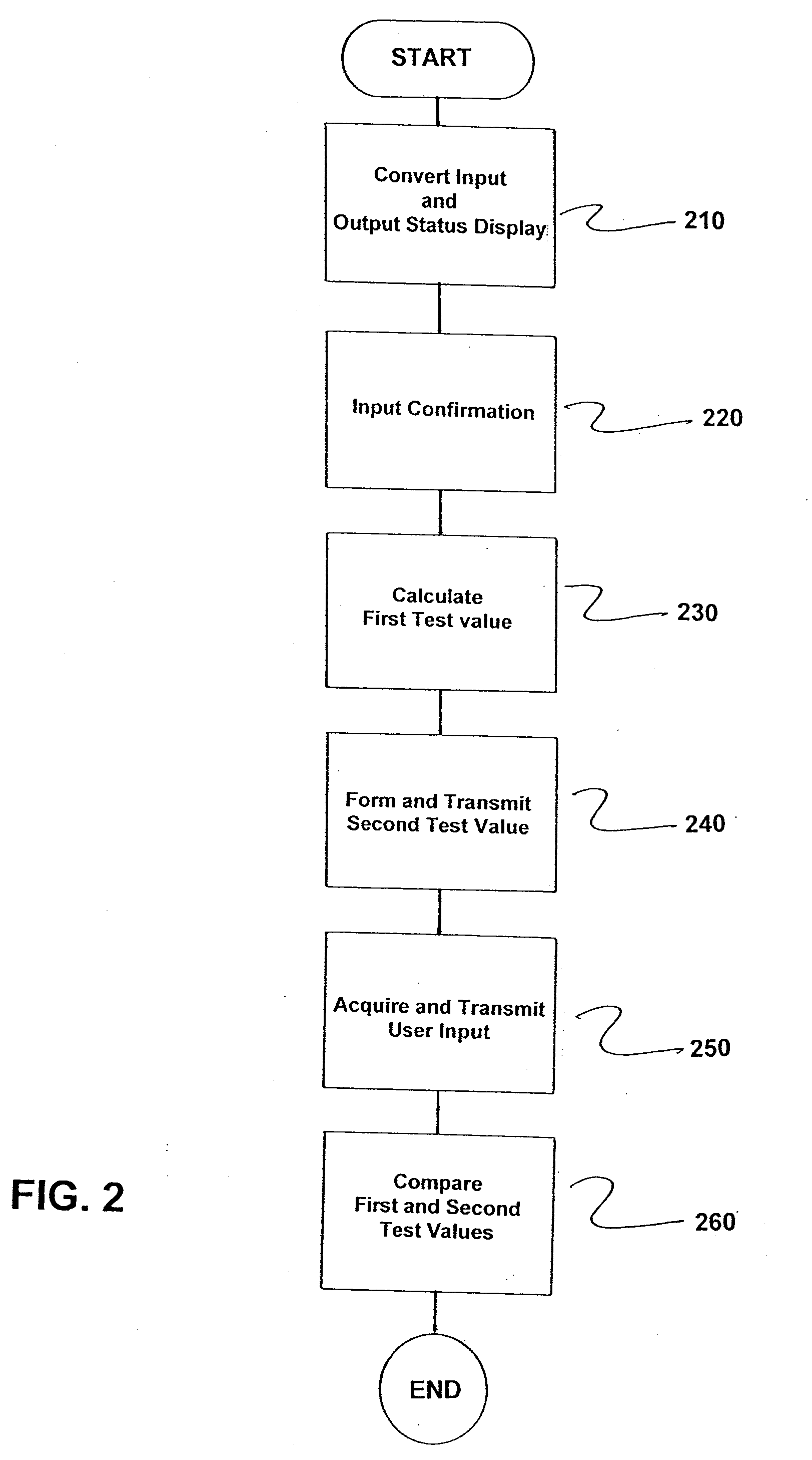
[0010]The practice of protecting access to the automation component based on the displays and inputs as part of a confirmation (acknowledgement) makes it possible to flexibly plan control functions in a controller with standard devices. As a result, a safety-oriented component advantageously need not be used for the controller itself, but rather means and methods which correspond to the standard device can be used for the controller and for data transmission between the controller and the safety-oriented industrial automation component. It is possible to dispense with the effort needed to create and program a safety-oriented (i.e., redundant, failsafe and certified) control station and likewise safety-oriented data transmission. A particular advantage is that it is thus ensured that precisely that information which was also displayed by and confirmed with the second dialog (i.e., the third and fourth steps) is used. The “what you see is what you get” (WYSIWYG) principle applies.
[0011]In accordance with the invention, a controller for a safety-oriented industrial automation component is also provided, where to perform one of the abovementioned methods, the controller comprises a first user interface for performing the first step, and a conversion unit and a second user interface for performing the third and fourth steps. A computation unit for performing the fifth step is also provided. Such a controller can be constructed with standardized device without having to pursue the increased effort for a safety-oriented technical concept. Such a controller can be used to safely input, confirm and transmit instructions, values or changes in values for a safety-oriented industrial automation component.
[0012]A plurality of inputs are advantageously made at the first user interface in a control step, a plurality of second test values being formed from this plurality of inputs in the controller and a plurality of first test values being formed from the results of the inputs in the automation component, where the plurality of first test values are combined to form a first total test value and the plurality of second test values are combined to form a second total test value. In the sixth step, the first total test value and the second total test value are compared with one another as the first and second test values. Alternatively, it is possible to directly convert all inputs into a total test value. As a result, it is also possible to protect different control steps or a plurality of values / changes in values using a single test step. On the one hand, the “workflow” is thus simplified for a user in that only a “collective” confirmation step is also necessary. On the other hand, computation complexity can be saved both by the controller and by the automation component.
[0014]In an embodiment, inputs that are directly transmitted by the first user interface to the second user interface inside the controller are used to output the status display in the third step. In an alternative embodiment, the inputs that were received by the automation component in the first step and were then transmitted back to the controller are used to output the status display. Whereas these inputs and data can be transmitted in a faster and simpler manner in the former case, the procedure described second can increase safety further because errors during the data transmission in the first step can also be discovered in this case with a greater degree of probability.

Problems solved by technology

Failsafe automation components are used wherever the health or life of people (or animals) may be adversely affected, or where there is the threat of a large amount of environmental or material damage in the event of failure or in the event of a malfunction.
Here, faults may occur, both in the “non-failsafe”controller and on the communication link, between the controller and the failsafe automation component, which faults influence the data to be transmitted, i.e., the information that changes the values of the parameters in the industrial automation component, such that erroneous values occur for the parameters of the failsafe automation component.

Method used


Image

  • Method and Controller for Controlling a Safety-Oriented Industrial Automation Component
  • Method and Controller for Controlling a Safety-Oriented Industrial Automation Component
  • Method and Controller for Controlling a Safety-Oriented Industrial Automation Component

Examples


Embodiment Construction

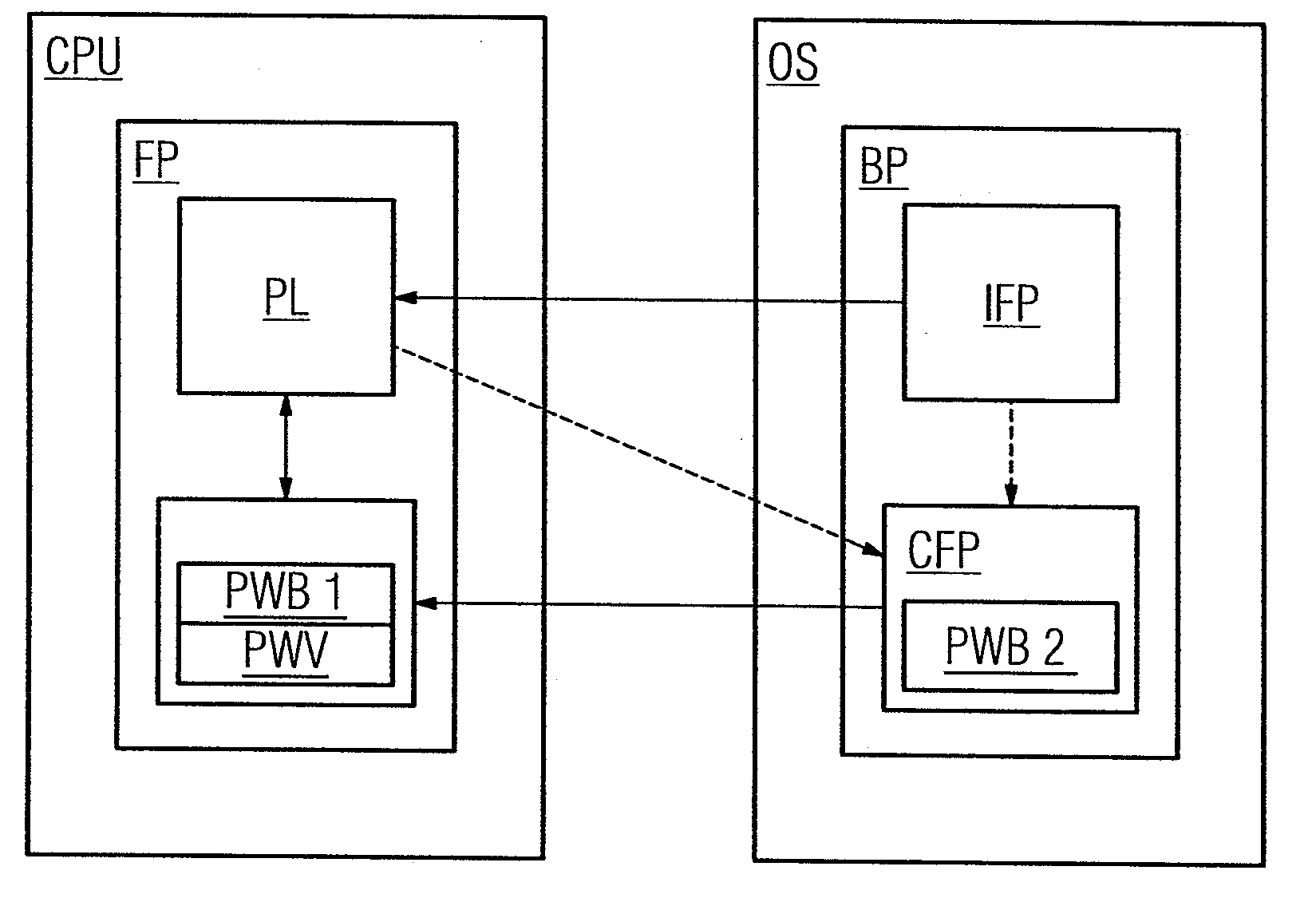
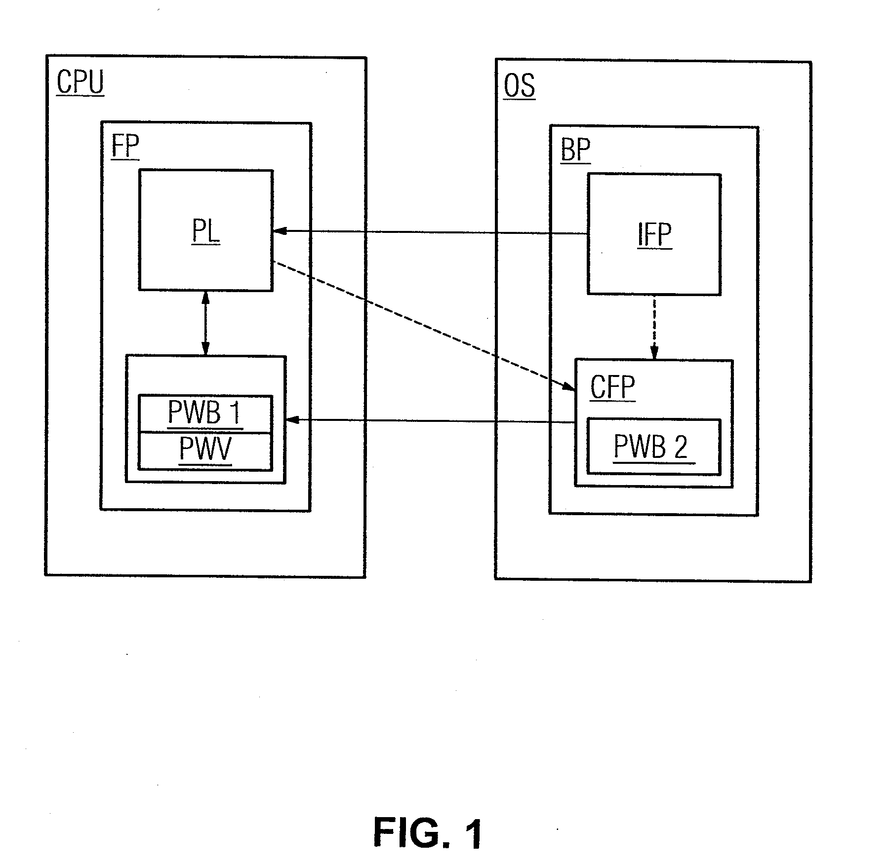
[0019]FIG. 1 illustrates safety-oriented (“failsafe”) industrial automation component (CPU) connected to the controller Operation Station (OS) through an information network (not shown). The automation component (CPU) is provided with safety-oriented software Failsafe Program (FP) comprising a parameter list (PL). The parameter list (PL) comprises variables, constants or information relating to settings i.e., all information which is intended to be input, retrieved and changed by the controller (OS). In addition to the parameter list (PL), the safety-oriented software (FP) comprises a further function block with the modules (PWB1) test value calculation 1 and test value comparison (PWV). In the present exemplary embodiment, the controller (OS) is not or is not necessarily in the form of a safety-oriented component, i.e., in contrast to the automation component (CPU), no special measures with regard to failure safety, certification or redundancy have been taken or have to be taken. I...


PUM


Abstract

A method for a safety-oriented industrial automation component, wherein the controller is connected to the automation component by a data link includes providing, by a user, an input to the controller at a first user interface. The controller transmits a result of the input to the automation component. The result of the input is used in the automation component to calculate a first test value. The input is converted into a status display in the controller and is output at a second user interface. Here, the user or another user acknowledges the status display by inputting a confirmation, after which a second test value is formed from the status display and the confirmation in the controller, and the second test value is transmitted to the automation component. Finally, the first and second test values are compared in the automation component and the result of the input is used if the comparison is positive.

Description

BACKGROUND OF THE INVENTION[0001]1. Field of the Invention[0002]The invention relates to industrial safety devices and, more particularly, to a method for controlling a safety-oriented industrial automation component, and to a controller for a safety-oriented industrial automation component.[0003]2. Description of the Related Art[0004]In industrial automation components, such as “CPUs” or “controllers”, a distinction is made between conventional automation components and so-called failsafe automation components or “F-CPUs”. Failsafe automation components are used wherever the health or life of people (or animals) may be adversely affected, or where there is the threat of a large amount of environmental or material damage in the event of failure or in the event of a malfunction. Such failsafe systems and controllers are regularly based on a hardware architecture in which the most important components are of redundant (i.e., duplicative) design. Furthermore, in the case of such compon...

Claims


Application Information

Patent Timeline
IPC IPC(8): G05B9/02
CPCG05B19/0428G05B2219/24191G05B2219/24188G05B2219/23258
Inventor TASCHKE, ULRICHWITTE, KARL-HERMANN
Owner SIEMENS AG
Learn More