
Fluid stream powered pulse generating fluidic oscillator

a fluidic oscillator and flow stream technology, applied in mechanical equipment, machines/engines, transportation and packaging, etc., can solve problems such as inability to solve problems, high input pressure, and difficulty in controlling frequency, and achieve the effect of enhancing the stability of oscillations

Active Publication Date: 2012-03-08
DLHBOWLES INC
View PDF3 Cites 10 Cited by
  • Summary
  • Abstract
  • Description
  • Claims
  • Application Information

AI Technical Summary

Benefits of technology

[0010]It is, therefore, an object of the present invention to overcome the above mentioned difficulties by providing an inexpensive, adjustable and reliable source of pulsed pressure liquid or gas.
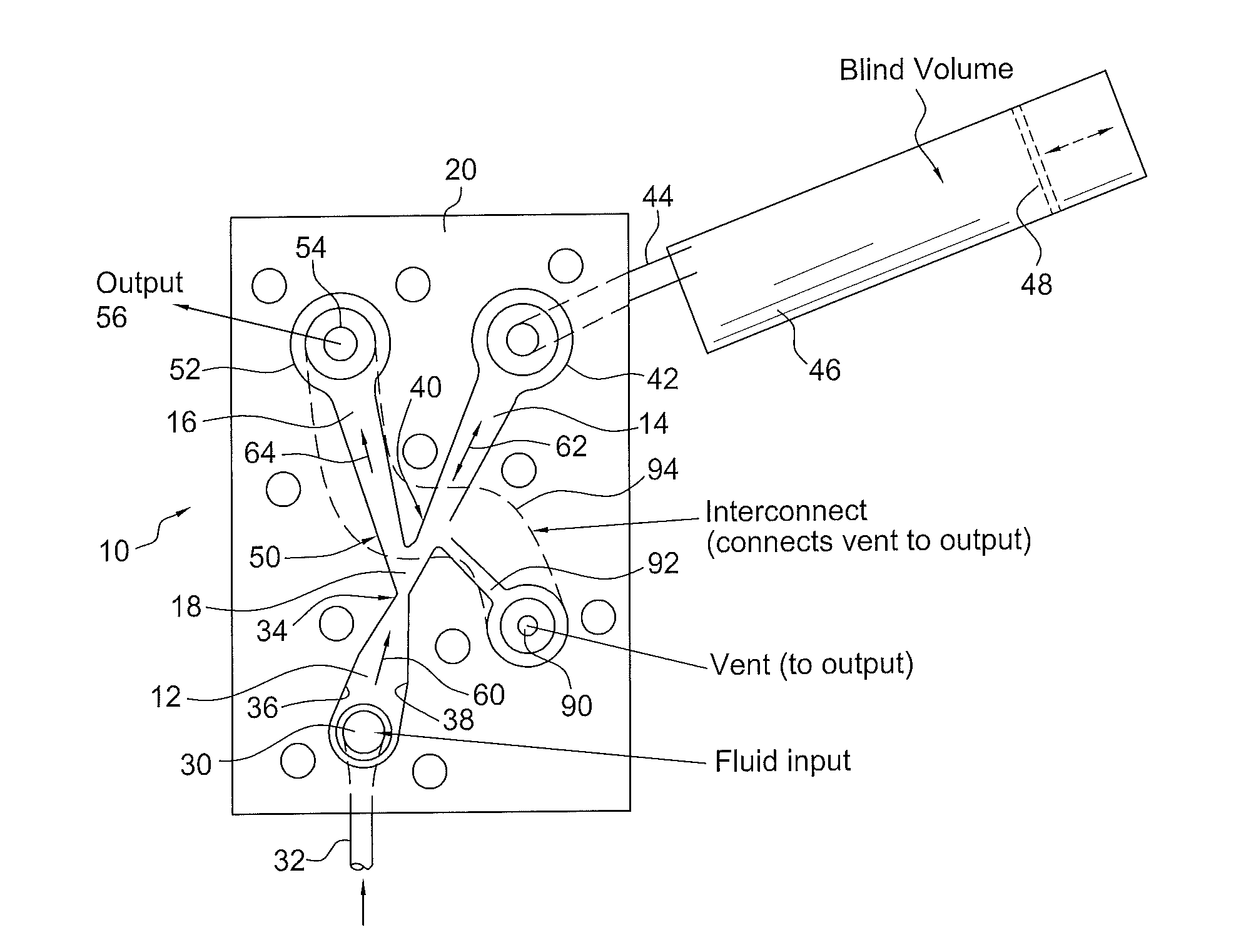
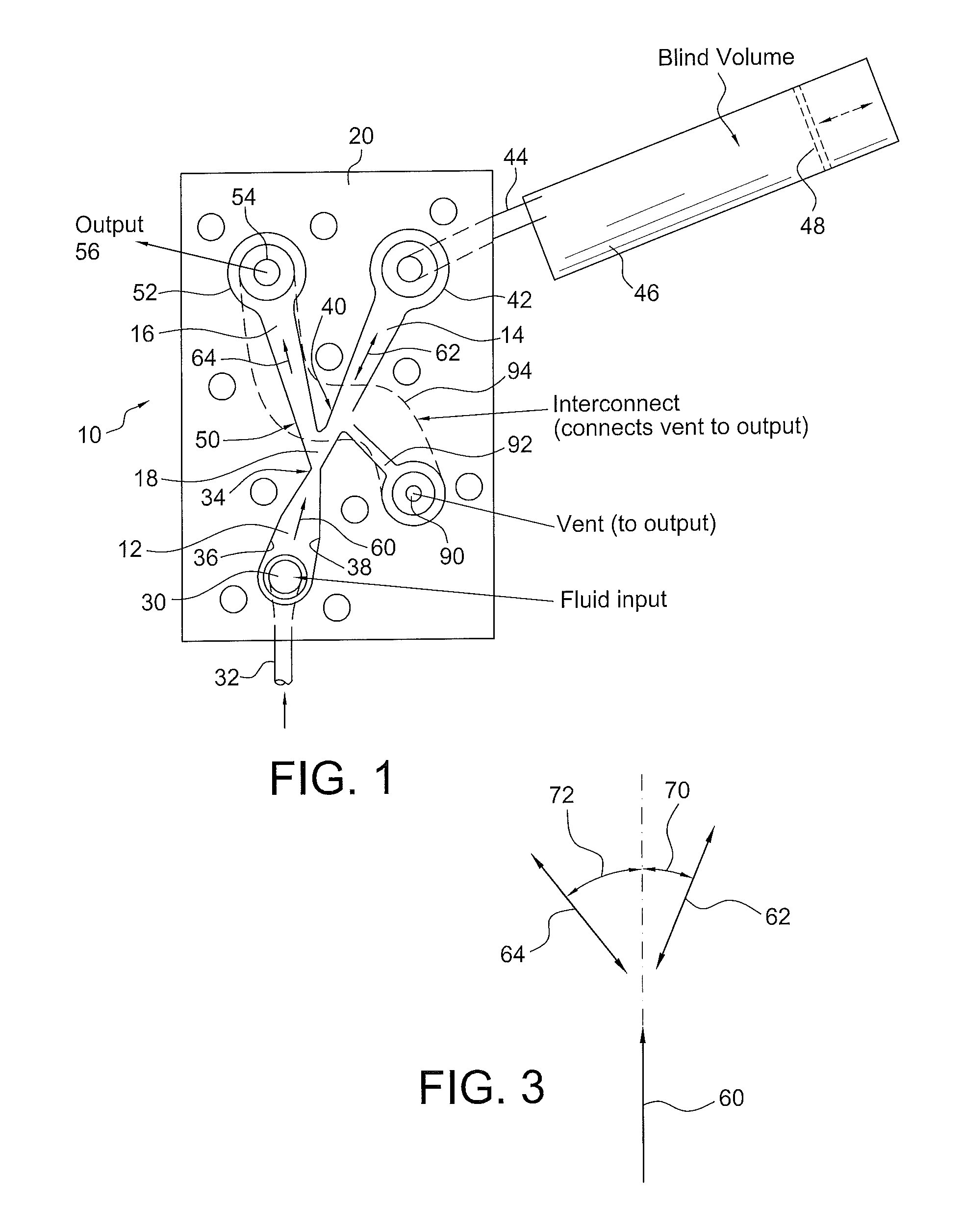
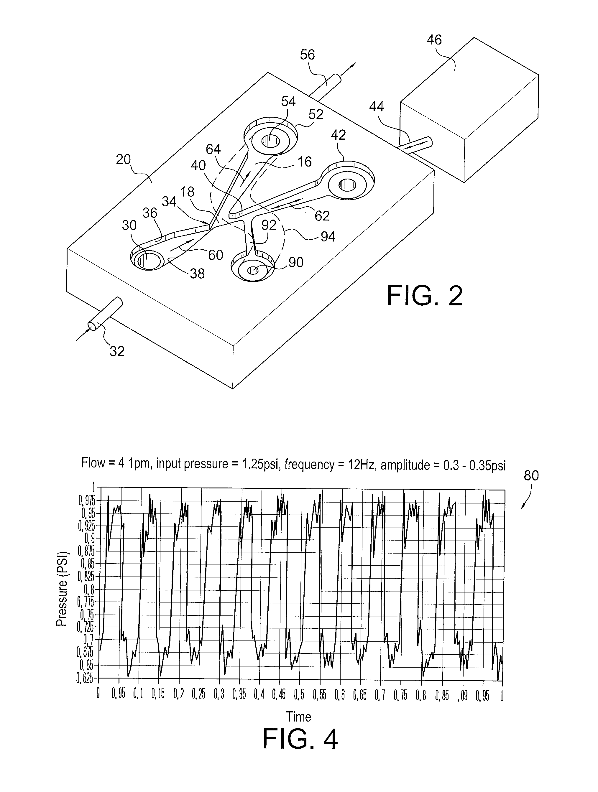
[0019]The amplitude of the pressure pulses can be controlled by the angle between the two legs of the Y and by the “inter-leg” angle between the outlet leg and the blind volume's leg, from the Y junction. The outlet end of the Y base, or inlet channel, terminates in a power nozzle lumen area at the distal or downstream terminus of the inlet leg, and this area and the lumen area of the output aperture or hole at the distal end of the right-hand, or outlet leg, are selected together to enhance the stability of the oscillations.
[0020]In an implementation of the pulse generator of the present invention, it was found that the pulser works best for air when the first, second and third channels have aspect ratios (AR) (depth / width) of 0.3-0.9, the vent hole lumen area is larger than the power nozzle area, and the output hole is considerably larger than the power nozzle area.

Problems solved by technology

Such systems typically utilize control circuits which periodically energize the pumps or which control switching valves to generate a desired sequence of pressurized pulses, but often require robust switching systems utilizing high-maintenance mechanical valving arrangements.
Other systems may utilize “check valves” which interrupt fluid flow to produce pressure pulses without the need for external control circuits, typically by the use of moving valve components in the flow path, but these have the disadvantage of requiring high input pressures and have frequencies that are difficult to control.
The complicated systems of the prior art are expensive to make and maintain, and utilize moving parts that often require continuous maintenance.
The '331 patent does not, however, describe a way of delivering a continuously pulsed supply of a fluid to an output, and thus does not solve the problems of earlier mechanical pulsed systems, but, nevertheless, is incorporated herein in it's entirely, to supplement the background of this disclosure.
Another commonly owned prior art fluidic oscillator is described in U.S. Pat. No. 6,805,164 to Stouffer, which discloses a structure for generating a time-varying flow of liquid only, but applicants have discovered that the '164 structure is not useful for generating pulses solely with air or another gas and is also not effective for use in liquid / gas micro-irrigation applications.
The '164 patent does not, however, describe a way of delivering a continuously pulsed supply of a gas to an output, does not provide a way of altering the frequency of the liquid jets and does not provide an adjustable structure and method for use in therapeutic applications such as micro-irrigation, but, nevertheless, is incorporated herein in it's entirely, to supplement the technical background of this disclosure.

Method used


Image

  • Fluid stream powered pulse generating fluidic oscillator
  • Fluid stream powered pulse generating fluidic oscillator
  • Fluid stream powered pulse generating fluidic oscillator

Examples


Embodiment Construction

[0028]Referring now to FIGS. 1-6, wherein similar components are similarly numbered, a gas or liquid adjustable fluidic circuit oscillator or pulsator device 10 is selectively configurable to produce pulses of gas or liquid fluid flow having a selected pulse repetition frequency, pulse duration, pulse peak pressure and pulse peak flow rate. The fluidic device 10 includes first, second and third fluid flow controlling channels 12, 14 and 16, respectively, which converge in a junction 18 to defining a “Y” configuration in which the first fluid flow channel 12 forms the base leg of the Y, the second fluid flow channel 14 forms the right-hand arm of the Y, and the third fluid flow channel 16 forms the left-hand arm of the Y. As illustrated more clearly in FIG. 2, the channels may be formed in a block 20 of a suitable material such as plastic, in known manner, and covered to provide enclosed first, second and third flow channels in fluid communication with one another and with a configur...


PUM


Abstract

A fluidic device which produces fluid pulses having a selected pulse repetition frequency, pulse duration, pulse peak pressure and pulse peak flow rate includes first, second and third fluid flow controlling channels or lumens which converge in a junction, defining a “Y” configuration having a base leg and right and left diverging arms. The first leg portion has a fluid input and terminates downstream at the Y junction of the base and the two diverging arms. The first leg has converging walls which reduce the cross sectional area of the flow to thereby increase the fluid velocity to make a fluid jet. The second or right leg, begins at the Y junction and terminates distally in an enclosed, fluid-tight container having a selected blind volume. The third, or left leg, begins at the Y junction and terminates distally in a fluid outlet passage having a selected cross-sectional area.

Description

[0001]This application claims the benefit of U.S. Provisional Application No. 61 / 334,266, filed 13 May 2010, and entitled “Fluid Stream Powered Pulse Generating Fluidic Oscillator”, The disclosure of which is hereby incorporated herein by reference.BACKGROUND OF THE INVENTION[0002]1. Field of the Invention[0003]The present invention relates to methods and apparatus for generating pressurized pulses of gas or liquid, and more particularly to a fluidic circuit responsive to an inlet fluid flow to produce a pulsed outlet fluid stream. Still more particularly, the invention is directed to a fluidic oscillator in which fluid flow pulses of selected pulse repetition frequency, pulse duration, peak pulse pressure and / or pulse peak flow rate are produced.[0004]2. Discussion of the Prior Art:[0005]As is well known, pneumatic pumps and electric pumps can be operated and controlled to generate periodic pulses of pressurized fluids such as liquids or gases. Such systems typically utilize contro...

Claims


Application Information

Patent Timeline
Patent Type & Authority Applications(United States)
IPC IPC(8): F15D1/00
CPCA61H9/0007F15C1/22A61H2201/5056A61H2201/5051Y10T137/0396Y10T137/2262Y10T137/2267Y10T137/8593
Inventor GOPALAN, SHRIDHARALLEN, KERRIERUSSELL, GREGORYTHURBER, JERRY
Owner DLHBOWLES INC
Learn More