Failure indicator seal for a rotary feedthrough

a technology of failure indicator and rotary feedthrough, which is applied in the direction of engine seals, resistance/reactance/impedence, instruments, etc., can solve the problems of loss of yield or complete ruination of products, slow and steady evaporation of oil, and difficult problem solving of dynamic rotary vacuum sealing

Inactive Publication Date: 2012-03-01
FERROTEC USA CORP
View PDF15 Cites 14 Cited by
  • Summary
  • Abstract
  • Description
  • Claims
  • Application Information

AI Technical Summary

Benefits of technology

[0017]For both of the above reasons, low evaporation rates and difficulty in defining bearing life, magnetic fluid feedthroughs are either replaced at unnecessarily short intervals or, alternatively, not replaced at all until they fail. Neither solution represents a satisfactory situation for a component often seen as having critical importance. It is advantageous to be able to monitor the condition of feedthroughs and signal their condition to operators or diagnostic equipment.
[0018]Therefore, it is an object of the present invention to provide a rotary feedthrough that is capable of indicating the condition of the rotary feedthrough. It is another object of the present invention to provide a rotary feedthrough that is capable of indicating the condition of the rotary feedthrough to enable maintenance when required of the feedthrough at a scheduled shut down. It is a further object of the present invention to provide a rotary feedthrough with a means to easily identify a potentially failing rotary feedthrough among a plurality of rotary feedthroughs. It is still another object of the present invention to provide a rotary feedthrough that is capable of providing an advanced warning of a potential problem with the rotary feedthrough. It is yet another object of the present invention to enable identification of a problem feedthrough in a degraded condition operating amongst a plurality of feedthroughs.

Problems solved by technology

Dynamic rotary vacuum sealing is a very difficult problem to solve particularly as any leak of atmospheric gases into the vacuum chamber can result in contamination of the product resulting in either loss of yield or complete ruination of the product.
However, it must be recognized that exposure of the magnetic fluid to a very high vacuum, particularly if the process is at a high temperature, can result in a slow and steady evaporation of the oil.
However, for high quality magnetic fluids, operating even at very high temperatures, the evaporation is at such an extremely low rate it takes place over many years.
Therefore, it makes any decision of “if” and “when” to service the feedthrough particularly difficult to define.
Feedthroughs, especially those operating at high speeds or high loads, are particularly demanding on the bearings.
These demands are magnified as bearing lubricants that are compatible with vacuum operation are not particularly good compared to conventional bearing lubricants.
Therefore, failure of the bearing within the vacuum environment is often observed while the bearing on the atmosphere side, often lubricated with a good quality conventional lubricant, remains in excellent condition.
There is little supporting data, however, on the demands of operating in a vacuum environment with relatively poor lubricants.
The wide variation in life over diverse operating conditions coupled with the large error band on any supporting data makes the definition of a suitable maintenance schedule very difficult.
For both of the above reasons, low evaporation rates and difficulty in defining bearing life, magnetic fluid feedthroughs are either replaced at unnecessarily short intervals or, alternatively, not replaced at all until they fail.

Method used


Image

  • Failure indicator seal for a rotary feedthrough
  • Failure indicator seal for a rotary feedthrough
  • Failure indicator seal for a rotary feedthrough

Examples


Embodiment Construction

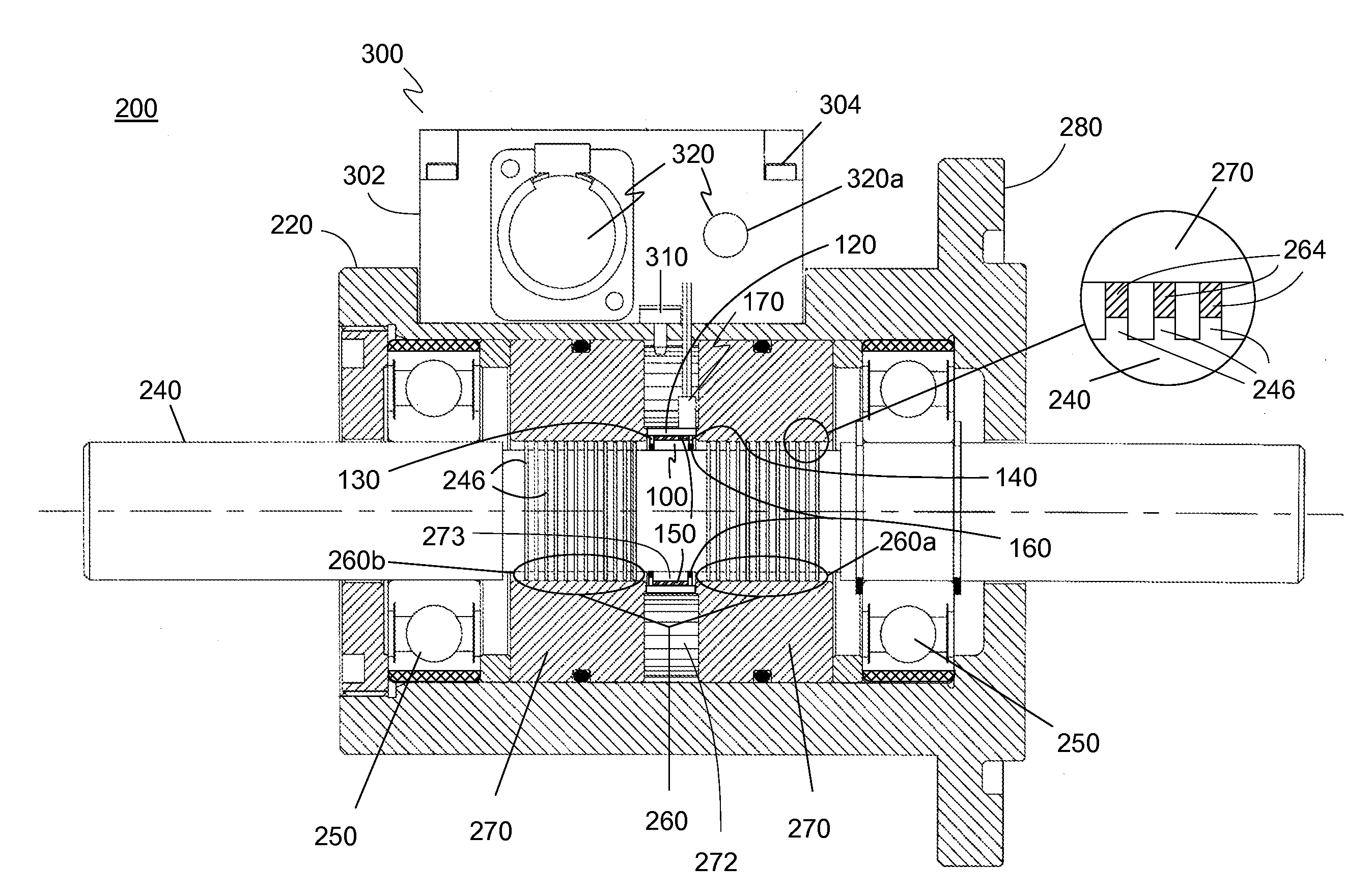
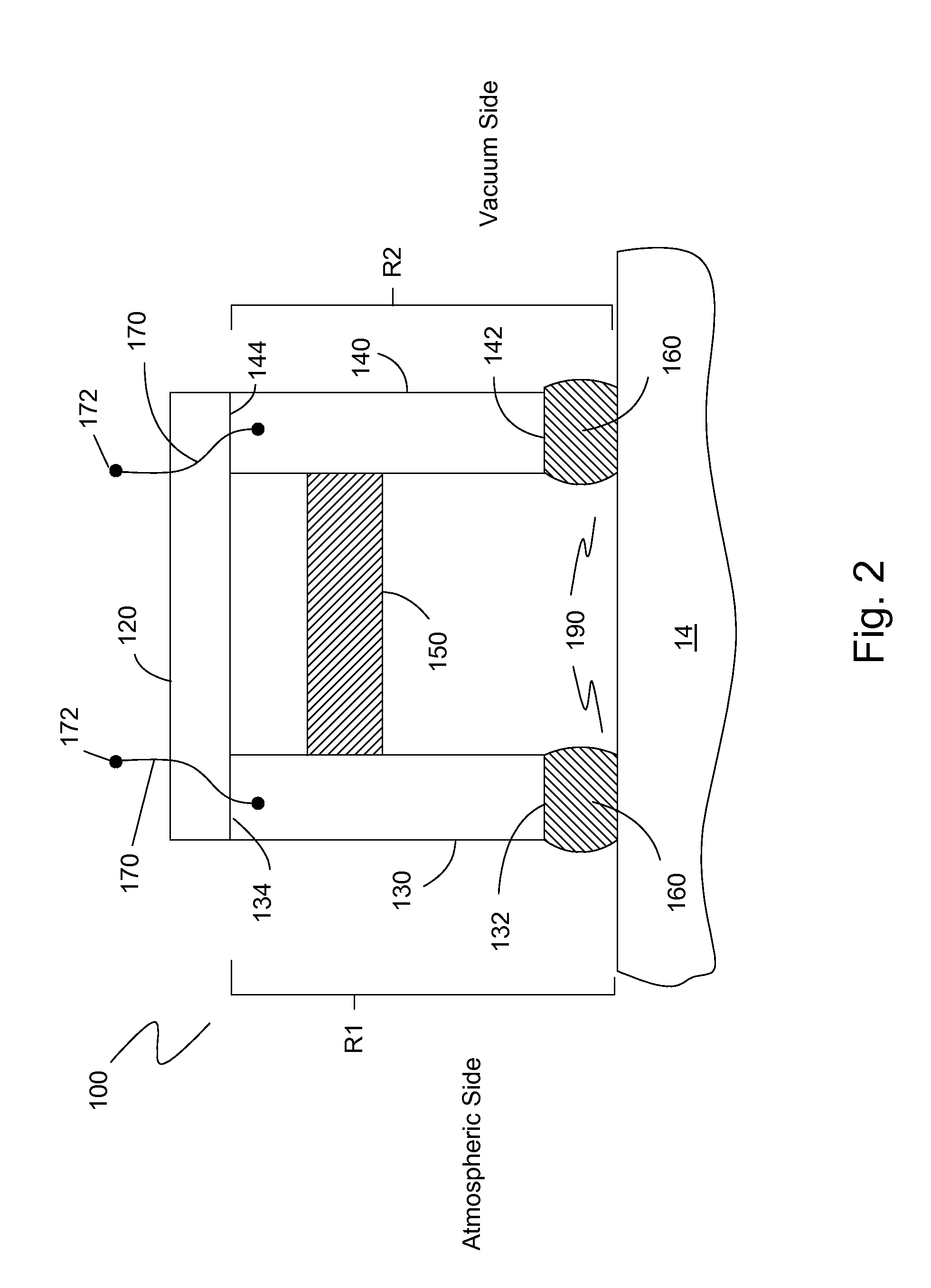
[0047]The preferred embodiment of the present invention is illustrated in FIGS. 2-7. FIG. 2 shows one embodiment of a failure indicator seal 100 in a partial cross-sectional view. Failure indicator seal 100 is incorporated into a magnetic fluid rotary feedthrough and uses resistance measurements to determine the condition of the magnetic fluid rotary feedthrough. Failure indicator seal 100 includes a housing 120, a first annular pole piece 130, and a second annular pole piece 140 adapted for disposing around a rotary shaft 14 of a magnetic fluid vacuum feedthrough 10 (not shown) that extends out of a feedthrough housing 12 (not shown). Failure indicator seal 100 also optionally includes an electrically non-conducting magnet 150 disposed between first pole piece 130 and second pole piece 140. Magnet 150 is optional since the magnet of the magnetic fluid vacuum feedthrough 10 may be used as the magnetic source instead of incorporating magnet 150. The magnet 150 may also be electricall...


PUM


Abstract

A failure indicator seal includes a nonmagnetic housing, a plurality of annular pole pieces having distal ends, the plurality of annular pole pieces disposed within the nonmagnetic housing, an annular, non-conducting magnet disposed between the pole pieces, a predefined quantity of magnetic fluid disposed between each of the distal ends of the plurality of annular pole pieces and the rotary shaft of a rotary feedthrough forming a plurality of magnetic fluid O-ring seals, and means for measuring resistance through the plurality of annular pole pieces, the plurality of magnetic fluid O-ring seals and the rotary shaft.

Description

BACKGROUND OF THE INVENTION[0001]1. Field of the Invention[0002]The present invention relates generally to the field of rotary feedthrough seals. Particularly, the present invention relates to a rotary feedthrough seal assembly.[0003]2. Description of the Prior Art[0004]Rotary feedthroughs have been developed for use in closed systems that may be under vacuum or at atmospheric pressure or at elevated pressure. These seals are typically high pressure mechanical seals. The function of these rotary feedthroughs is to provide a virtually hermetic, rotating seal. There are basically two types of rotary feedthrough seals. These include mechanical seals such as, for example, where O-rings are positioned around a shaft or where magnetic fluid and its accompanying magnetic system are positioned around a shaft.[0005]Magnetic fluid feedthroughs have been developed for use in vacuum systems where they perform the function of providing a virtually hermetic rotating seal. These products rely on t...

Claims


Application Information

Patent Timeline
Patent Type & Authority Applications(United States)
IPC IPC(8): G01R27/08F16J15/43
CPCF16J15/43F16J15/3296
Inventor RAJ, KULDIP
Owner FERROTEC USA CORP
Why Eureka
Try Eureka