
Glass Interposer Panels And Methods For Making The Same

a technology of glass substrate core and glass core, which is applied in the direction of resistive material coating, cable/conductor manufacturing, metallic material coating process, etc., can solve the problems of limited input/output density, high thermal mismatch, and poor dimensional stability of organic interposer panels, and achieve greater strength of glass substrate cores

Inactive Publication Date: 2012-03-01
CORNING INC
View PDF2 Cites 146 Cited by
  • Summary
  • Abstract
  • Description
  • Claims
  • Application Information

AI Technical Summary

Benefits of technology

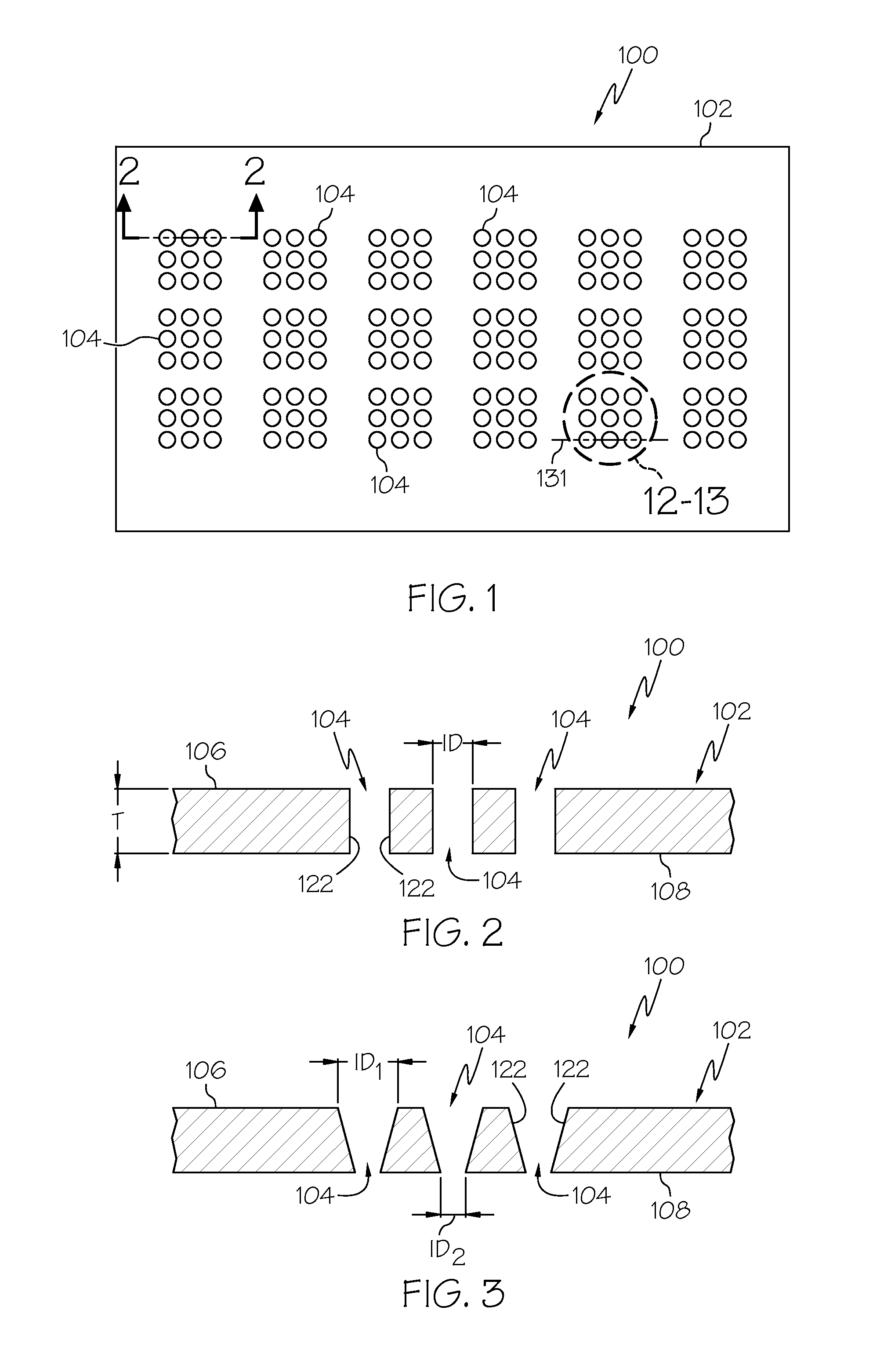
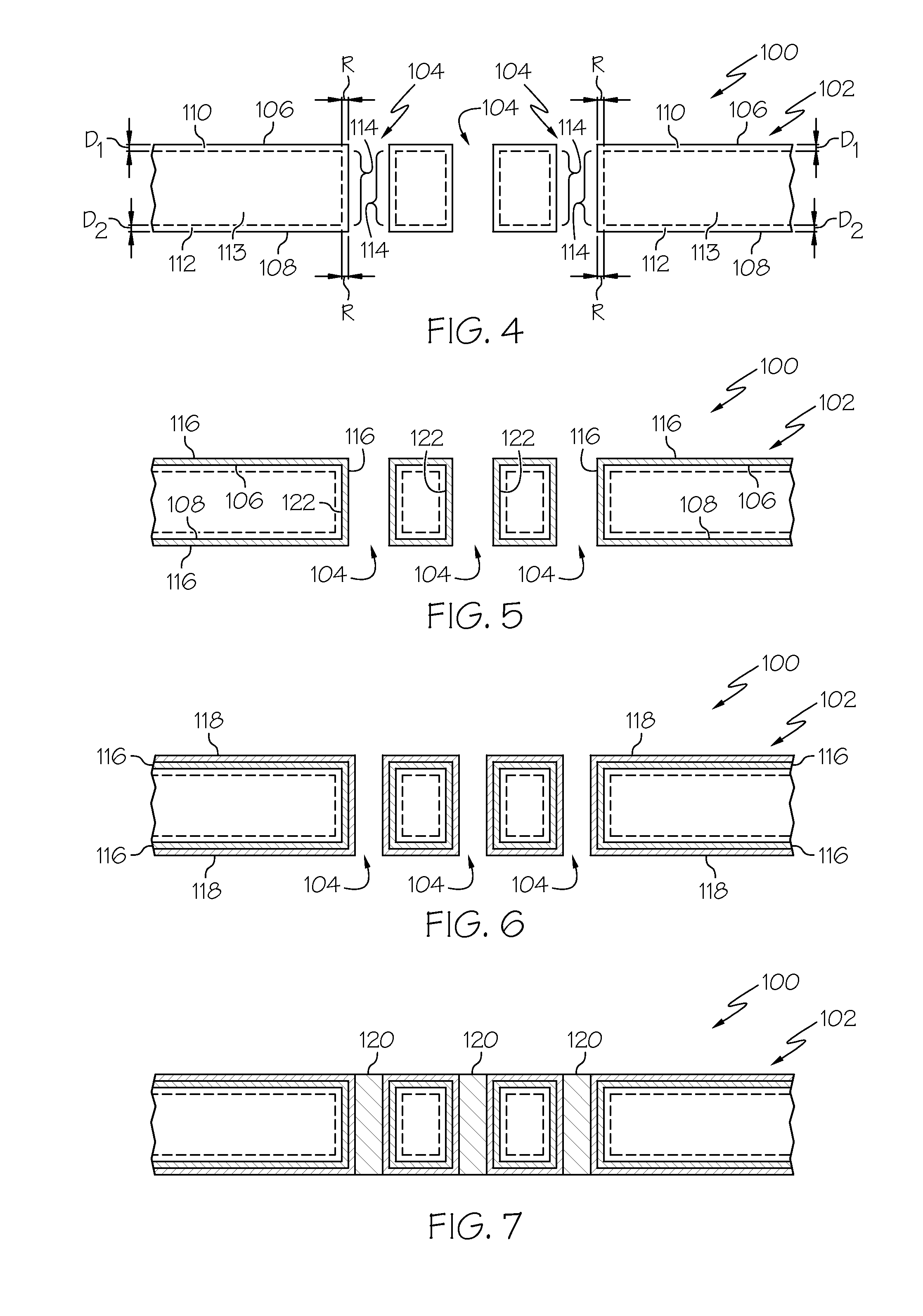
The patent describes an interposer panel for an electronic assembly that includes a glass substrate core. The glass substrate core has a first layer of compressive stress on its first surface and a second layer of compressive stress on its second surface. The panel also has a plurality of through-vias that are surrounded by intermediate zones of compressive stress. The compressive stress layers and the through-vias improve the strength and reliability of the interposer panel. The method for making the panel involves forming the through-vias and then inducing the compressive stress layers. The strengthened glass substrate core can also be used in other electronic assemblies.

Problems solved by technology

However, organic interposer panels exhibit poor dimensional stability and high thermal mismatch with common integrated circuit materials, such as silicon, which, in turn, limits the input / output density and the achievable miniaturization of the electronic assembly.
Further, organic interposer panels exhibit poor thermal conductivity which also limits the achievable power density of the electronic assembly.
However, silicon interposer panels are relatively expensive to produce and are limited in size.

Method used


Image

  • Glass Interposer Panels And Methods For Making The Same
  • Glass Interposer Panels And Methods For Making The Same
  • Glass Interposer Panels And Methods For Making The Same

Examples


example 1

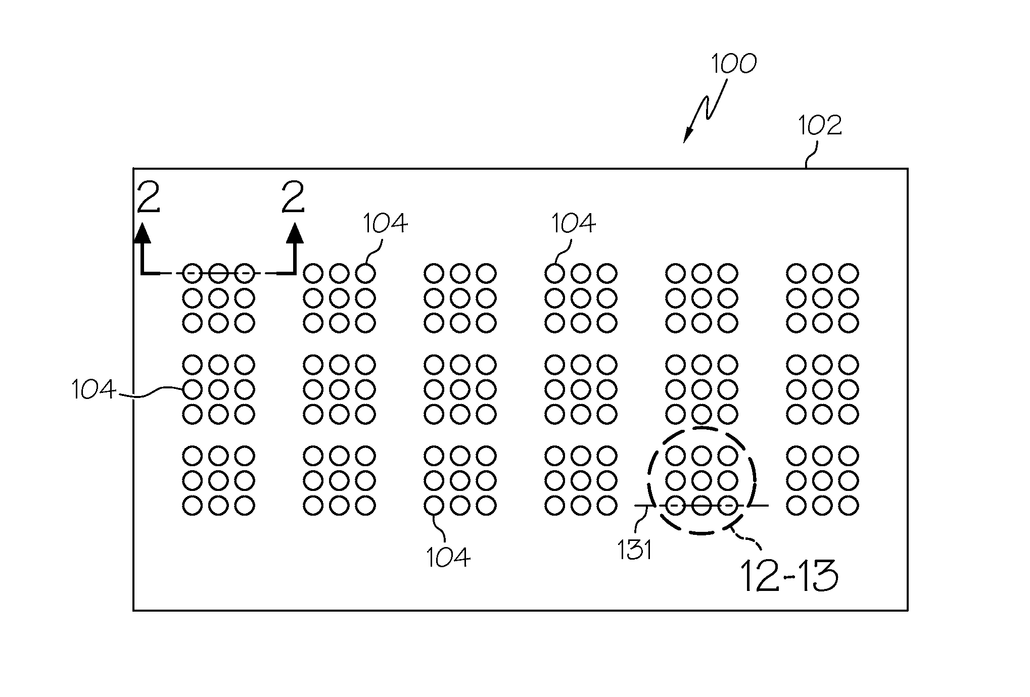
[0057]Threes sets of 50 mm×50 mm glass interposer panels were formed from Gorilla™ alkali aluminosilicate glass. Each glass interposer panel had a thickness of 0.7 mm. In this example, a single through-via having a diameter of 1 mm was mechanically drilled at the center of each glass interposer panel, as indicated in FIG. 9. A first set of glass interposer panels were then mechanically tested to failure in as-drilled condition (i.e., without further processing) using ring-on-ring testing. The applied stress at failure (i.e., the failure stress) was recorded.

[0058]A second set of glass interposer panels were chemically etched in a solution of HF:HCl:20H2O for 15 minutes to remove defects from the surfaces of the glass interposer panels and from the through-vias. Each of the glass interposer panels in the second set of glass interposer panels was then mechanically tested to failure using ring-on-ring testing. The applied stress at failure for each glass interposer panel was recorded.

[...

example 2

[0061]Three sets of 50 mm×50 mm glass interposer panels were formed from Gorilla™ alkali aluminosilicate glass. Each glass interposer panel had a thickness of 0.7 mm. In this example, five through-vias were mechanically drilled in the glass interposer panel in a cross-configuration, as indicated in FIG. 10. Each through-via had a diameter of 1 mm and an edge-to-edge spacing of 300 microns. A first set of glass interposer panels was mechanically tested to failure in as-drilled condition (i.e., without further processing) using ring-on-ring testing. The applied stress at failure (i.e., the failure stress) was recorded.

[0062]A second set of glass interposer panels were chemically etched in a solution of HF:HCl:20H2O for 15 minutes to remove defects from the surfaces of the glass interposer panels and from the through-vias, as described above. Each of the glass interposer panels in the second set of glass interposer panels was mechanically tested to failure using ring-on-ring testing. T...

example 3

[0065]Threes sets of 50 mm×50 mm glass interposer panels were formed from Gorilla™ alkali aluminosilicate glass. Each glass interposer panel had a thickness of 0.7 mm. In this example, a single through-via having a diameter of 1 mm was laser drilled at the center of each glass interposer panel using a femtosecond laser trepanning technique. A first set of glass interposer panels were then mechanically tested to failure in as-drilled condition (i.e., without further processing) using ring-on-ring testing. The applied stress at failure (i.e., the failure stress) was recorded.

[0066]A second set of glass interposer panels were chemically etched in a solution of HF:HCl:20H2O for 15 minutes to remove defects from the surfaces of the glass interposer panels and from the through-vias. Each of the glass interposer panels in the second set of glass interposer panels was then mechanically tested to failure using ring-on-ring testing. The applied stress at failure for each glass interposer pane...


PUM

PropertyMeasurementUnit
radial thicknessaaaaaaaaaa
compressive stressaaaaaaaaaa
thicknessaaaaaaaaaa

Abstract

Glass interposer panels and methods for forming the same are described herein. The interposer panels include a glass substrate core formed from an ion-exchangeable glass. A first layer of compressive stress may extend from a first surface of the glass substrate into the thickness T of the glass substrate core to a first depth of layer D1. A second layer of compressive stress may be spaced apart from the first layer of compressive stress and extending from a second surface of the glass substrate core into the thickness T of the glass substrate core to a second depth of layer D2. A plurality of through-vias may extend through the thickness T of the glass substrate core. Each through-via is surrounded by an intermediate zone of compressive stress that extends from the first layer of compressive stress to the second layer of compressive stress adjacent to a sidewall of each through-via.

Description

BACKGROUND[0001]1. Field[0002]The present specification generally relates to interposer panels for electronic package assemblies and, more specifically, to glass interposer panels for electronic assemblies formed from strengthened glass.[0003]2. Technical Background[0004]A current trend in the miniaturization of electronic devices is the 3D integration of electronic components, such as 3D integrated circuits, on a single substrate such that the electronic components are stacked thereby forming a more compact package. A driving force for this trend is consumer demand for mobile and handheld electronic devices and higher density I / Os as chips become increasingly complex.[0005]Currently, organic interposer panels are commonly integrated into 3D electronic assemblies due to their low cost and ease of manufacture. However, organic interposer panels exhibit poor dimensional stability and high thermal mismatch with common integrated circuit materials, such as silicon, which, in turn, limit...

Claims


Application Information

Patent Timeline
Patent Type & Authority Applications(United States)
IPC IPC(8): H05K1/02H05K3/00
CPCC03C15/00H05K1/0306Y10T29/49165H05K3/4038C03C21/002Y10T29/49117H05K2201/09563Y10T29/49155H05K2201/10378H05K2201/0769H05K1/115H01L23/49827H01L23/15
Inventor CORNEJO, IVAN A.GOMEZ, SINUEHARRIS, JAMES MICHEALMOORE, LISA ANNETSUDA, SERGIO
Owner CORNING INC
Learn More