Apparatus for collecting oil escaped from an underwater blowout

a technology for escaping oil and apparatus, which is applied in the direction of underwater drilling, drilling machines and methods, and borehole/well accessories, etc. it can solve the problems of leaking oil in the steel casing and the underlying rock formation, leaking oil, and blowout, etc., and achieves the effect of facilitating pressure equalization

Inactive Publication Date: 2012-02-02
IVIC MICHAEL
View PDF42 Cites 6 Cited by
  • Summary
  • Abstract
  • Description
  • Claims
  • Application Information

AI Technical Summary

Benefits of technology

[0013]The tubular member has an open top, which facilitates pressure equalization between the water and the interior of the tubular member. Escaped oil and gas ascend to the water surface being guided by the tubular member. To reduce solidification of paraffin and methane icing, a portion of the tubular conduit if formed from polyvinyl chloride.

Problems solved by technology

Several problems accompany deep-sea drilling and production, one of which is position of the wellhead a mile or more below the water surface.
When the production pipe is damaged, the steel casings and the underlying rock formations are leaking oil, under a considerable pressure into the water.
If the BOP fails, a catastrophic blowout can occur, as a result of which the wellhead and the formation around it starts leaking oil.
In the offshore drilling or production of oil and gas, accidents such as equipment malfunctions or the like occasionally result in a condition known as a blowout.
In such instances, the fluids under substantial underground pressure flow uncontrollably to the surrounding body of water.
The contamination caused by a blowout disastrously affects the environment.
A non-checked oil spill can kill every sea inhabitant and wildlife along a nearby shoreline.
However, to control the flow from a burning or damaged well, it is necessary to close the wellbore at a location where the casing and tubing are still undamaged and accessible.
These procedures, however, are hazardous, costly and time consuming.
As the additional wellbores are drilled, which can take several months in an offshore location, the oil continues to flow onto and pollute the surrounding area.
Moreover, in an offshore operation, heavy wave action severely limits the available options.
In spite of advanced technology and substantial safety measures, there is always a risk of accidents caused by e.g. human error, material fatigue, system malfunctioning or the influence of forces of nature.
The escaped oil rises to the surface and disperses with resulting pollution and detrimental effects to bird life and the environment of marine biology.
Furthermore, the blown pipe may have uneven edges, which makes sealing of the pipe even more difficult.

Method used


Image

  • Apparatus for collecting oil escaped from an underwater blowout
  • Apparatus for collecting oil escaped from an underwater blowout

Examples


Embodiment Construction

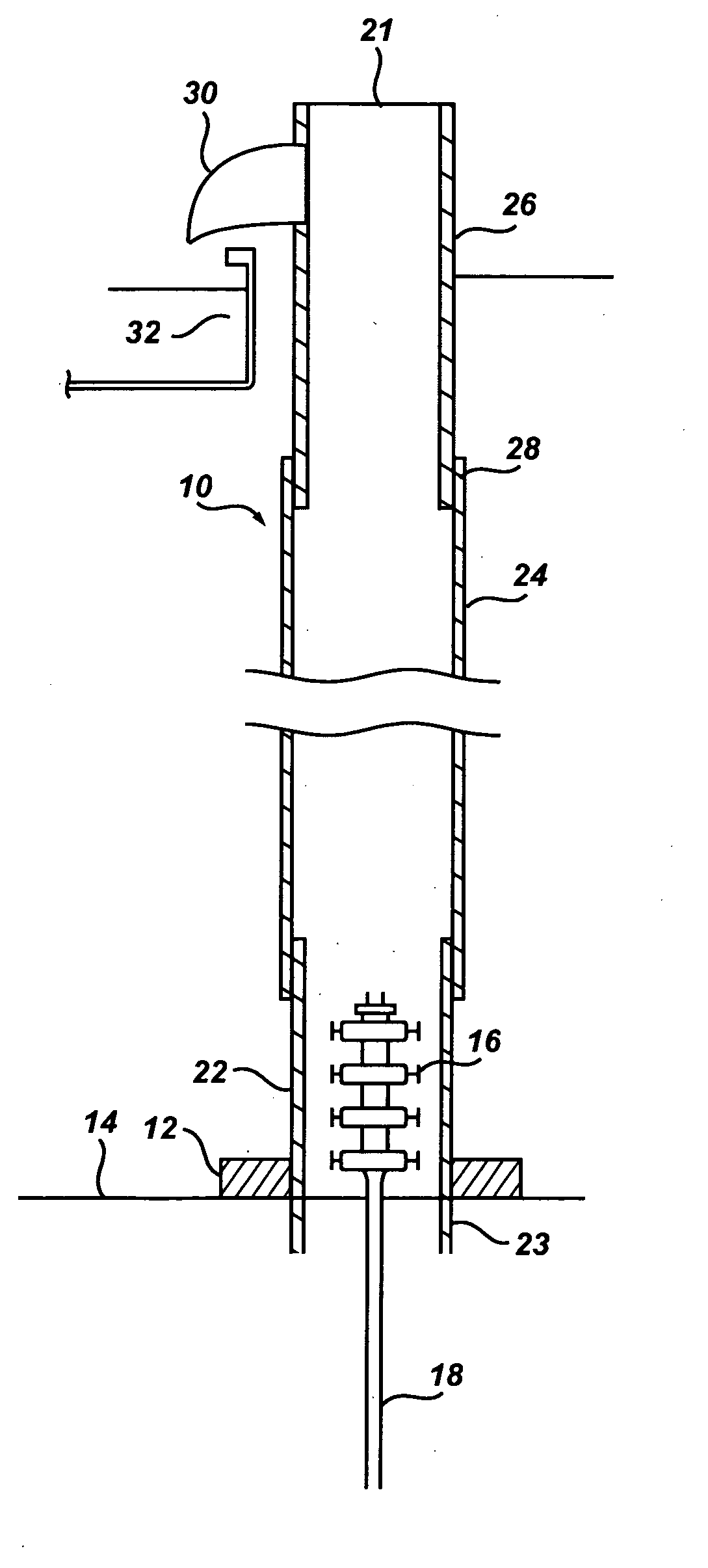
[0017]As apparent from FIGS. 1 and 2, the apparatus 10 comprises a ring-shaped base 12 configured to rest on a sea bottom 14 in a surrounding relationship to a wellhead 16. The base has a central opening configured to receive a tubular channeling member 20 therethrough, as will be explained in more detail hereinafter.

[0018]The wellhead 16 can be in the form of a conventional subsea Christmas tree, with a plurality of valves for regulating a flow of liquids to and from a drill pipe or production pipe 18. Conventionally, the drill / production pipe 18 penetrates the formation to reach a producing zone (not shown), while the Christmas tree 16 is mounted in the upper part of the drill / production pipe 18.

[0019]The base 12 is preferably formed as a weighted non-buoyant member that resists displacement by the water current. If one aspect of the invention, the base 12 is a ring-shaped hollow body filled with concrete to assure an appropriate seal between a bottom surface 15 of the base 12 wit...


PUM


Abstract

A large diameter conduit extends from a subsea location surrounding a wellhead to an area above the water surface. The conduit is designed to channel escaped oil and gas from the underwater well to a floating collection facility. The conduit has a portion formed from polyvinyl chloride to reduce paraffin solidification and methane gas icing.

Description

BACKGROUND OF THE INVENTION[0001]The present invention relates to an apparatus for collecting oil escaped from an underwater wellhead into a surrounding body of water. More particularly this invention relates to an apparatus for channeling escaped oil from a point near the seabed to a floating oil collection facility.[0002]In recent years, the exploitation of oil and gas deposits in geological layers deep beneath the sea surface has become more and more common. The exploitation of these energy resources comprises several phases from the drilling of test wells up to and including the establishment of production facilities. Test drilling as well as production is often conducted from offshore structures, such as floating rigs, semi-submersible vessel and bottom-secured platforms.[0003]Several problems accompany deep-sea drilling and production, one of which is position of the wellhead a mile or more below the water surface. When the production pipe is damaged, the steel casings and the...

Claims


Application Information

Patent Timeline
Patent Type & Authority Applications(United States)
IPC IPC(8): E21B43/01
CPCE21B43/0122
Inventor IVIC, MICHAEL
Owner IVIC MICHAEL
Why Eureka
Try Eureka