Rainscreen clapboard siding

Active Publication Date: 2006-10-10
CERTAINTEED CORP
View PDF45 Cites 33 Cited by
  • Summary
  • Abstract
  • Description
  • Claims
  • Application Information

AI Technical Summary

Benefits of technology

[0008]The designed air gap allows for air flow between overlapping panels, thereby helping to promote air circulation between the panels. This circulation promotes pressure equalization between the front and rear faces of the siding panel and eliminates a factor known to contribute to rain penetration.
[0010]The designed air flow path between overlapping siding panels helps to promote air circulation between the panels. This circulation promotes pressure equalization between the front and rear faces of the siding panel and eliminates a factor known to contribute to rain penetration.

Problems solved by technology

This penetration can cause rotting and decay and has been identified as the cause of massive condominium failures in regions such as Nova Scotia.
This overlap can cause a pressure imbalance between the outer and inner surfaces of the overlapping panels, thereby providing the force necessary to draw water into the assembly towards the wall.
A related issue is draining water away from the wall once it penetrates the assembly.
This helps reduce the amount of moisture that is pulled to the rear face of the siding panel, which can lead to moisture-related problems such as mold growth or wall rotting stemming from collected water or moisture.
The use of furring strips, however, is not without its disadvantages, including increased installation costs due to the extra materials and the cumbersome installation process.

Method used


Image

  • Rainscreen clapboard siding
  • Rainscreen clapboard siding
  • Rainscreen clapboard siding

Examples


first embodiment

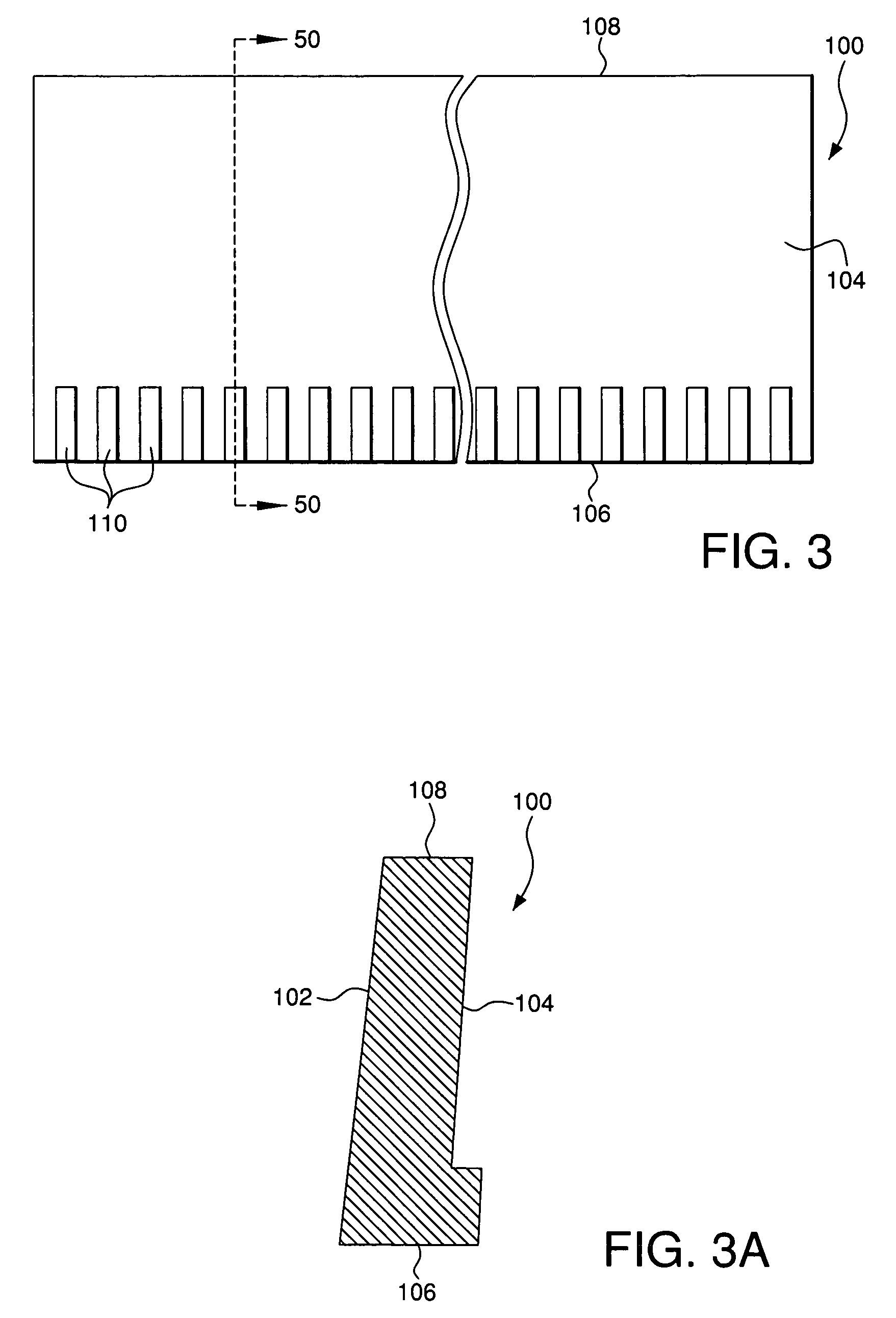
[0022]Referring first to FIG. 3, a rear elevational view of a siding panel 100 is shown. A cross-sectional view of the panel 100 taken along lines 50—50 is shown in FIG. 3A. Siding panel 100 has a generally rectangular shape, and, in an exemplary embodiment, is a clapboard siding panel, preferably a fiber cement clapboard siding panel. Siding panel 100 has front and rear faces 102 and 104, respectively. In one embodiment, the siding panel may be between about 12′–16′ in length, as is conventional, with faces about 10″ in height. The siding panel has a thickness typically between about ⅛ to ½″, and preferably around 3 / 16″. In one exemplary embodiment shown in the rear elevational view of FIG. 3 and the cross-sectional view of FIG. 3A, the panel 100 includes at least one, and preferably a plurality, of protrusions 110 located proximate to the bottom edge 106 of the panel and extending from the rear face 104. It should be understood, however, that the spaced protrusions 110 may extend ...

second embodiment

[0024]FIGS. 4–4C illustrate a siding panel and siding panel assembly that creates an air flow path that provides for pressure equalization as described above. FIG. 4 is a rear elevational view of a siding panel 200. FIG. 4A is a cross sectional view of the panel 200 taken along line 60—60 of FIG. 4. Like panel 100, siding panel 200 has a generally rectangular shape, and, in an exemplary embodiment, is a clapboard siding panel, preferably a fiber cement clapboard siding panel. Siding panel 200 has front and rear faces 202 and 204, respectively. In the embodiment shown in the rear elevational view of FIG. 4 and the cross-sectional view of FIG. 4A, the panel 200 includes at least one, and preferably a plurality, of recesses 210 that are located proximate to the bottom edge 208 of the panel 200 and within the rear face 204. It should be understood, however, that a plurality of spaced recesses 210 may be formed within the rear face 204 proximate to the bottom edge 206 of the panel 200 an...


PUM


Abstract

A generally rectangular siding panel having a front and rear faces is provided. The siding panel has at least one protrusion disposed along at least one of the faces, wherein the at least one protrusion provides an air gap between the siding panel and a face of a second siding panel when the siding panels are installed in a siding panel assembly. A generally rectangular siding panel having a front and rear faces is also provider where the siding panel has at least one recess or cut spaced along at least one of the faces, wherein the at least one recess or cut provides an air flow path between the siding panel and a face of a second siding panel when the siding panels are installed in a siding panel assembly.

Description

FIELD OF THE INVENTION[0001]The present invention relates to siding products and methods of installing siding products, and more particularly to apparatuses and methods for providing rainscreen in overlapping siding panels.BACKGROUND OF THE INVENTION[0002]Typically, clapboard siding panels, such as fiber cement clapboard siding panels, are installed on a wall of a structure, generally on a sheathing product, in one of two ways—either in a so called “blind nail” method or a so called “face nail” method. In the blind nail method, illustrated by siding panel assembly 20 of FIG. 2, a first siding panel 16a is aligned on the face of a wall 12 and a nail (not shown) is driven through the panel 16a, generally through an upper region of the exterior face of the panel 16a, into the wall 12. A second panel 16b is then secured to the wall 12 in the same manner using nail 18. The second panel 16b overlaps a portion of the exterior face of the first panel 16a and covers the nail or fastener driv...

Claims


Application Information

Patent Timeline
IPC IPC(8): E04B1/00E04F13/08
CPCE04F13/0864
Inventor BECK, DAVID HERBERT
Owner CERTAINTEED CORP
Why Eureka
Try Eureka