
Image processing method and image processing apparatus

a technology of image processing which is applied in the field of image processing method and image processing apparatus, can solve the problems of high pressure, deformation of thermal recording medium, and deformation of flexibility, and achieve the effect of achieving durability and high quality imag

Inactive Publication Date: 2012-01-19
RICOH KK
View PDF4 Cites 7 Cited by
  • Summary
  • Abstract
  • Description
  • Claims
  • Application Information

AI Technical Summary

Benefits of technology

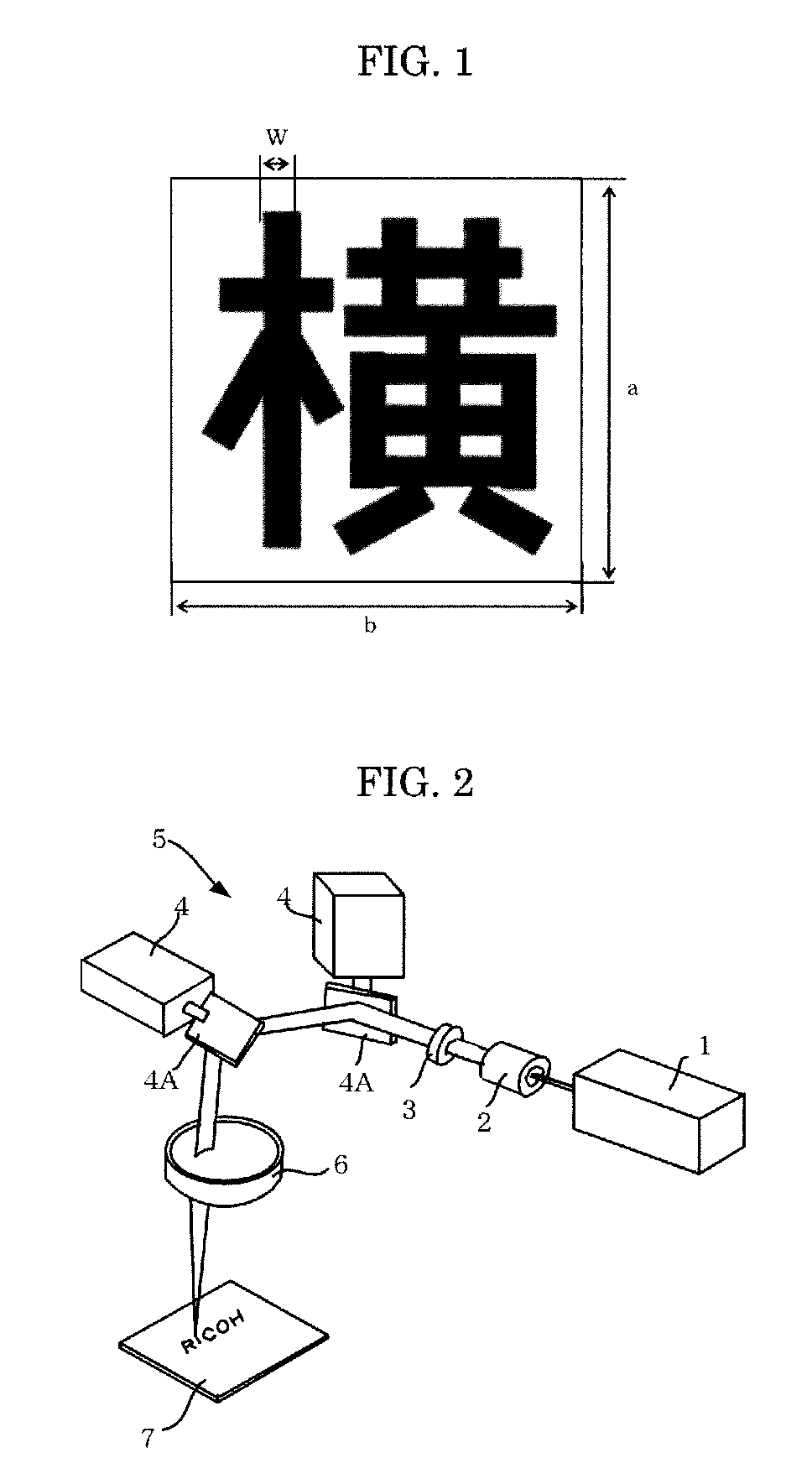
[0012]The present invention aims to provide an image processing method and an image processing apparatus, which can record high quality image having less bleeding by calculating a density of a character to be recorded based on information of a type, size, and line width of the character to be recorded, and adjusting an irradiation energy of the laser beam according to the density, and can attain durability against repeated use in the case of using a thermoreversible recording medium.
[0014]The present invention solves the conventional problems, and can achieve the object, and can provide an image processing method and an image processing apparatus, which can record high quality image having less bleeding by calculating a density of a character to be recorded based on information of a type, size, and line width of the character to be recorded, and adjusting an irradiation energy of the laser beam according to the density, and can attain durability against repeated use in the case of using a thermoreversible recording medium.

Problems solved by technology

However, when an RF-ID tag as disclosed in Japanese Patent Application Laid-Open (JP-A) No. 2004-265247 and Japanese Patent (JP-B) No. 3998193 is embedded in a thermoreversible recording medium, the thermoreversible recording medium needs to be thickened and the flexibility thereof degrades, and thus high pressure is required for uniformly pressing a heat source against the thermoreversible recording medium.
In addition, in the contact image processing method, a surface of the thermoreversible recording medium is scraped due to repetitive printing and erasure and irregularities are formed therein, and some parts are not in contact with a heating source, such as a thermal head, and hot stamp.
Thus, the thermoreversible recording medium may not be uniformly heated, causing degradation in image density and erasing failure (see Japanese Patent (JP-B) No. 3161199 and Japanese Patent Application Laid-Open (JP-A) No. 09-30118).
However, there is a problem that the time required for image recording and erasing becomes long, due to jump and waiting time between drawing lines.
However, since printing is performed by heat, thermal diffusion adversely affects printing, and this causes a problem that when a small character is printed, character bleeding occurs, causing degradation of visibility.

Method used


Image

  • Image processing method and image processing apparatus
  • Image processing method and image processing apparatus
  • Image processing method and image processing apparatus

Examples


production example 1

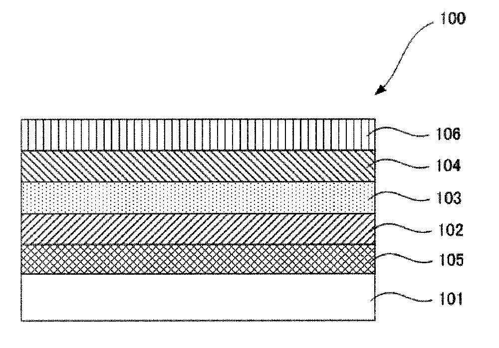
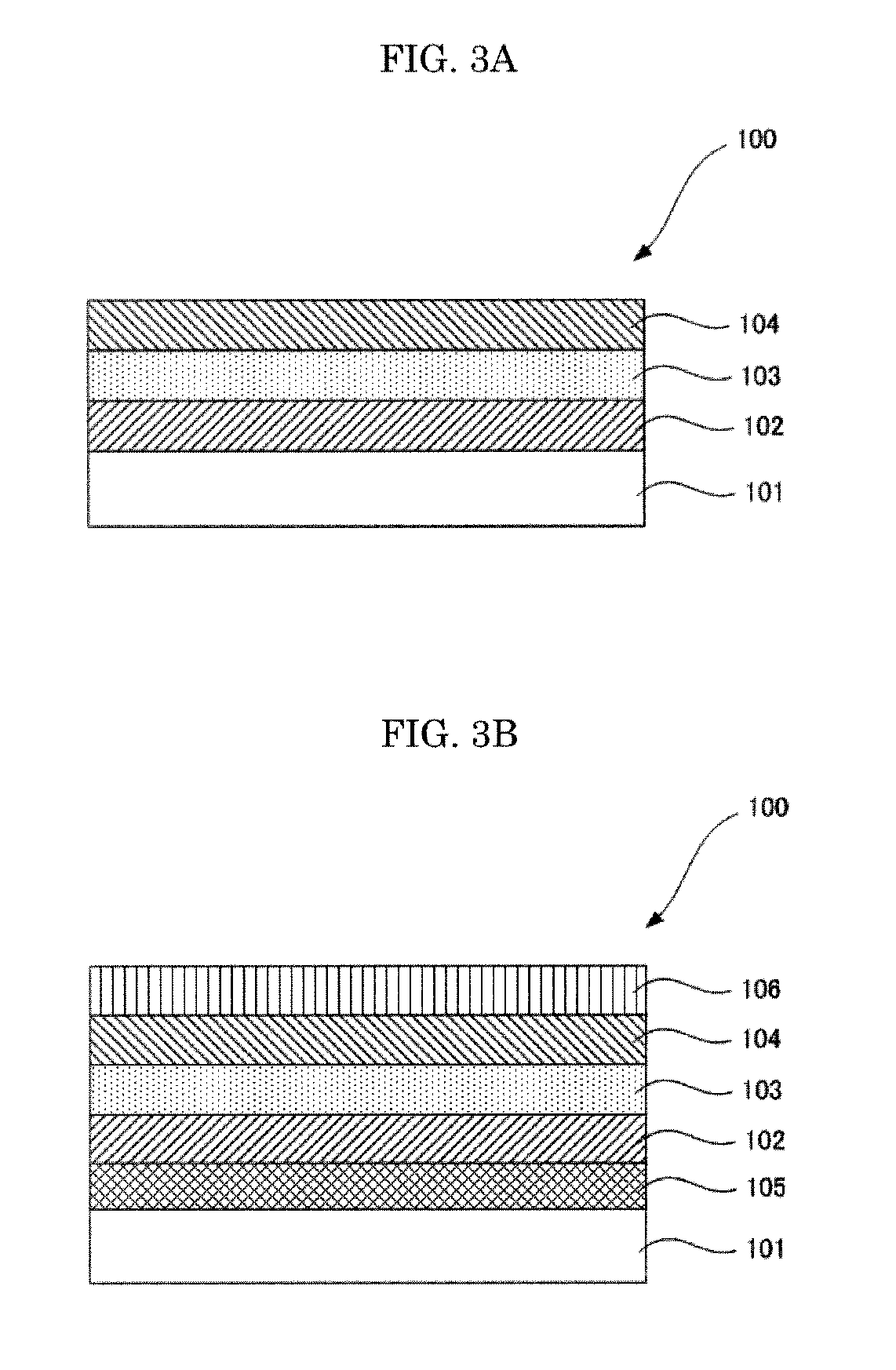
[0224]A thermoreversible recording medium capable of reversibly changing in color tone by heat was produced in the following manner.

—Support—

[0225]As a support, a white turbid polyester film of 125 μm in thickness (TETRON FILM U2L98W, produced by Teijin DuPont Films Japan Limited) was used.

—Formation of First Oxygen Barrier Layer

[0226]A urethane-based adhesive (produced by Toyo-Morton Ltd., TM-567) (5 parts by mass), 0.5 parts by mass of isocyanate (produced by Toyo-Morton Ltd., CAT-RT-37), and 5 parts by mass of ethyl acetate were mixed and sufficiently stirred to prepare an oxygen barrier layer coating liquid.

[0227]Next, the oxygen barrier layer coating liquid was applied onto a silica-deposited PET film (produced by Mitsubishi Plastics Inc., TECHBARRIER HX, oxygen permeability: 0.5 mL / m2 / day / MPa) using a wire bar, heated and dried at 80° C. for 1 minute. This silica-deposited PET film provided with the oxygen barrier layer was bonded on the support, and then heated at 50° C. for...

production example 2

—Production of Thermoreversible Recording Medium—

[0238]A thermoreversible recording medium of Production Example 2 was produced in the same manner as in Production Example 1, except that as the photothermal conversion material instead of the phthalocyanine photothermal conversion material, 2 parts by mass of a solution of 0.5% by mass of cyanine photothermal conversion material (YKR-2900, produced by Yamamoto Chemicals, Inc.; absorption peak wavelength: 830 nm) was added, and sufficiently stirred to prepare a photothermal conversion layer coating liquid. The cyanine photothermal conversion material (YKR-2900, produced by Yamamoto Chemicals, Inc.) was added in the amount that gave the same sensitivity of the thermoreversible recording medium as that of Production Example 1.

production example 3

—Production of Thermoreversible Recording Medium—

[0239]A thermoreversible recording medium of Production Example 3 was produced in the same manner as in Production Example 1, except that in the first thermoreversible recording layer as the photothermal conversion material an inorganic photothermal conversion material (lanthanum boride liquid, produced by Sumitomo Metal Mining Co., Ltd.) was added while the amount of the inorganic photothermal conversion material was adjusted so that the thermoreversible recording medium of Production Example 3 had the same sensitivity as the thermoreversible recording medium of Production Example 1, followed by forming the first thermoreversible recording layer having a thickness of 12 μm, and that the first oxygen barrier layer, the second oxygen barrier layer, the photothermal conversion layer, and the second thermoreversible recording layer were not formed.


PUM


Abstract

An image processing method including calculating a density of a character to be recorded based on information of a type, size and line width of the character; adjusting an irradiation energy of a laser beam for recording the character based on the density of the character; and irradiating a recording medium with the laser beam whose irradiation energy is adjusted so as to record the character thereon.

Description

BACKGROUND OF THE INVENTION[0001]1. Field of the Invention[0002]The present invention relates to an image processing method and an image processing apparatus, capable of recording high quality image having less printing bleeding.[0003]2. Description of the Related Art[0004]Image recording and image erasing on a thermoreversible recording medium as a recording medium have been carried out so far by a contact method in which a heating source is brought into contact with the thermoreversible recording medium to heat the thermoreversible recording medium. As the heating source, in the case of image recording, a thermal head is generally used, and in the case of image erasing, a heat roller, a ceramic heater or the like is generally used.[0005]Such a contact image processing method has advantage in that, if a thermoreversible recording medium is a flexible material such as paper, an image can be uniformly recorded and erased by evenly pressing a heating source against the thermoreversibl...

Claims


Application Information

Patent Timeline
IPC IPC(8): B41J2/435
CPCG06K15/021G06K15/029B41J2/4753G06K15/128G06K15/1209
Inventor ISHIMI, TOMOMIKAWAHARA, SHINYAASAI, TOSHIAKIHOTTA, YOSHIHIKO
Owner RICOH KK
Learn More