
Multi-cladding optical fiber, optical fiber module, fiber laser, and fiber amplifier

Inactive Publication Date: 2011-12-15
THE FUJIKURA CABLE WORKS LTD +1
View PDF1 Cites 18 Cited by
  • Summary
  • Abstract
  • Description
  • Claims
  • Application Information

AI Technical Summary

Benefits of technology

[0035]The above-described aspects of the present invention can provide an optical fiber having a simple structure and in which substantial single-mode propagation and enlargement of the effective core cross-sectional area are possible. Also, by using the optical fiber, it is possible to provide an optical fiber module, a fiber laser and a fiber amplifier with good optical characteristics.

Problems solved by technology

However, in the method disclosed in Non-patent Document 1, the cut-off wavelength ends up being lengthened together with the enlargement of the effective core cross-sectional area, and giving rise to the problem of a trade-off occurring between the single-mode propagation required for maintaining beam quality and effective core cross-sectional area enlargement.
Moreover, in the refractive index profile of the optical fiber that is disclosed in Non-patent Document 1, there has also been the problem of the effective core cross-sectional area becoming significantly smaller when the fiber is used in a bent condition (a detailed study result is given in Optical Express, 14, pp.
Also, the method that is disclosed in Non-patent Document 2 has been comparatively widely used recently, but as disclosed in Proceedings of OFC / NFOEC 2008, OTuJ2 (2008) (hereinafter abbreviated as Non-patent Document 9), there have been the problems of being the presence of a limit in enlargement of the effective core cross-sectional area affected by a reduction in the effective core cross-sectional area when bent, and as a result, it is impossible to sufficiently enlarge the effective core cross-sectional area, and in consideration of a bent condition, the outer diameter of the core being essentially limited to around 25 μm (320 μm2 when converted to the effective core cross-sectional area).
Also, in the methods disclosed in Non-patent Documents 3 and 4, since these fiber structures are sensitive to bending, it cannot be used in a bent condition, and so the problem arises of not being able to realize a compact fiber amplifier and fiber laser.
The method disclosed in Non-patent Document 5 is the same as the method disclosed in Non-patent Documents 3 and 4 on the point of the leakage fiber being sensitive to bending, and since the transmission loss is principally large, there is the problem of raising the lasing efficiency of the laser or amplifying efficiency of the amplifier being difficult.
The methods disclosed in Non-patent Documents 6 to 8 can effectively remove higher-order modes, but the refractive index profile and fiber structure is extremely complicated, and moreover since extremely high precision controls of refractive index profile and fiber structure are required, there have been the problems that fiber manufacturing is difficult, as a result, the manufacturing costs become high, and the yields become low.

Method used


Image

  • Multi-cladding optical fiber, optical fiber module, fiber laser, and fiber amplifier
  • Multi-cladding optical fiber, optical fiber module, fiber laser, and fiber amplifier
  • Multi-cladding optical fiber, optical fiber module, fiber laser, and fiber amplifier

Examples


example 1

[0131]An optical fiber having the refractive index profile and outer diameter as shown in FIG. 3B was manufactured.

[0132]First, the core and the inner cladding were manufactured by the MCVD method. A starting silica tube is heated, with an oxy-hydrogen flame from the outer side serving as the heat source, and tetrachlorosilane, a germanium tetrachloride, oxygen, and helium are supplied to inside the tube and reacted, and an inner cladding and core that consist of a layer of germanium-doped silica glass having the desired refractive index are formed on the inner wall surface of the start silica tube. The relative refractive index difference between the core, the inner cladding, and the intermediate cladding (start silica tube) is adjusted by the germanium doping amount of the core and the inner cladding. Afterward, the outer side of the tube is heated with an oxyhydrogen flame serving as the heart source in the same manner as describe above, and collapsed to be solidified while intro...

example 2

[0137]An optical fiber was manufactured having the same refractive index profile and outer diameter as Example 1.

[0138]After forming the inner cladding on the inside wall surface of the starting silica tube by the same method as Example 1, deposition of the core portion is performed and a porous glass layer is formed. Next, by immersing the interior of the tube in a mixed aqueous solution of aluminum chloride and ytterbium chloride for several hours and then drying it, aluminum and ytterbium that are the dopants of the core are introduced, and while thereafter introducing oxygen., helium and thionyl chloride in the tube, sintering (transparentizing) with a induction heating furnace as a heat source and collapsing were performed to solidify it. At this time, the relative refractive index difference between the core and the inner cladding becomes the desired value by adjusting the doping of aluminum and ytterbium.

[0139]Next, the ratio of the outer diameter of the intermediate cladding...

example 3

[0141]An optical fiber was manufactured having the same refractive index profile and outer diameter as Example 1.

[0142]First, the core and the inner cladding were formed by the VAD method. The core was formed with germanium-doped silica glass, and the inner cladding was formed with =doped silica glass.

[0143]Next, the intermediate cladding was formed by the outer vapor-phase deposition method. At the time, during sintering of the outer vapor-phase deposited portion, helium and silicon tetrafluoride are injected to make the refractive index lower than the inner cladding.

[0144]Next, similarly to the case of Example 1, drawing, the formation of the outer cladding, and the formation of the protective coating layer were performed. Note that the ratio of the outer diameter of the core and the outer diameter of the inner cladding, and the ratio of the outer diameter of the intermediate cladding and the outer diameter of the core are the same as those of Example 1.

[0145]For the optical fiber...


PUM


Abstract

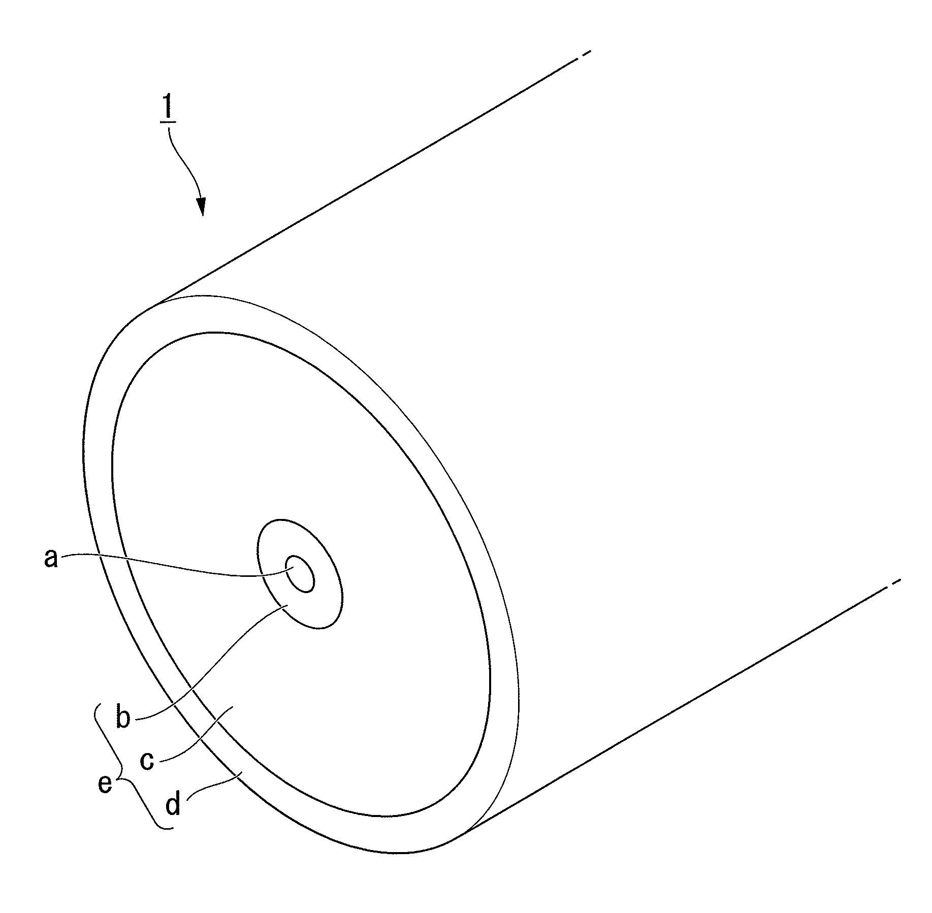
Provided is a multi-cladding optical fiber which includes: a core with an average refractive index n1; and a cladding including an inner cladding with an average refractive index n2 formed on the periphery of the core, an intermediate cladding with an average refractive index n3 formed on the periphery of the inner cladding, and an outer cladding with an average refractive index n4 formed on the periphery of the intermediate cladding where n1>n2>n3>n4. Two or more axisymmetric modes exist in the core at a wavelength of the signal light; the two or more axisymmetric modes including a fundamental mode and at least a high-order mode. When the fiber is bent at a predetermined bending diameter, the high-order mode in the core disperses within the inner cladding due to coupling with an inner cladding mode, so that only the fundamental mode substantially propagates through the core.

Description

CROSS REFERENCE TO RELATED APPLICATIONS[0001]This application is a continuation application based on a PCT Patent Application No. PCT / JP2010 / 003745, filed Jun. 4, 2010, whose priority is claimed on Japanese Patent Application No. 2009-144630 filed Jun. 17, 2009, the entire content of which are hereby incorporated by reference.BACKGROUND OF THE INVENTION[0002]1. Field of the Invention[0003]The present invention relates to a multi-cladding optical fiber that is suited to the transmission of high-power light, an optical fiber module that has the optical fiber, a fiber laser and a fiber amplifier.[0004]2. Description of the Related Art[0005]In recent years, there have been dramatic advances in the output power level of fiber amplifiers and fiber lasers. Accompanying these advances in increased output power, improvements in endurance to high-power light have been desired for various optical fiber components such as rare earth-doped optical fibers that are applied to fiber amplifiers and ...

Claims


Application Information

Patent Timeline
IPC IPC(8): H01S3/067G02B6/028
CPCG02B6/02033G02B6/03638H01S3/06733H01S3/06704G02B6/14
Inventor TANIGAWA, SHOJIICHII, KENTAROTAKENAGA, KATSUHIROSAITOH, KUNIMASA
Owner THE FUJIKURA CABLE WORKS LTD
Learn More