
Photoelectromethanogenic microbial fuel cell for co-generation of electricity and methane from carbon dioxide

a photoelectromethanogenic and fuel cell technology, applied in the direction of fuel cells, biochemical equipment and processes, biochemical apparatus, etc., can solve the problems of high amine cost, chemical degradation of amines, and significant threat to global climate stability, and achieve the effect of increasing the number of amines

Inactive Publication Date: 2011-12-08
CARBONITUM ENERGY CORP
View PDF2 Cites 12 Cited by
  • Summary
  • Abstract
  • Description
  • Claims
  • Application Information

AI Technical Summary

Benefits of technology

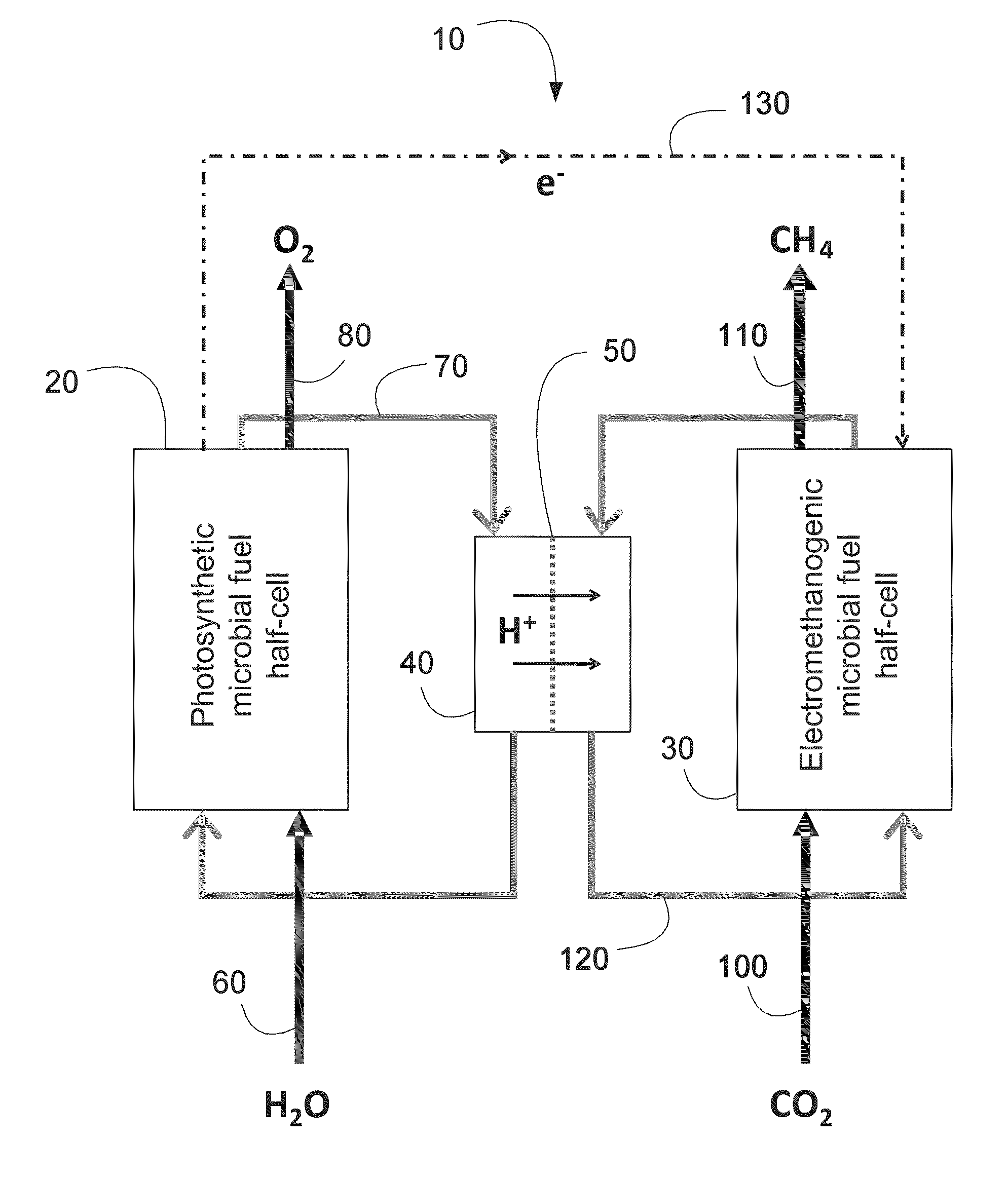
[0010]Other exemplary embodiments of the present invention relate to systems comprising one or more sets of coupled PMFhC components and EMFhC components that receive CO2 captured from flue gases emitted by stationary plants that combust fossil fuels in their operations. Exemplary embodiments of the systems are generally configured for receiving flue gases which are then cooled for separation and recovery of water from the other flue gas constituents exemplified by CO2, O2, N2, NO2, SO2, and fly ash of inorganic oxides among others. According to one aspect, the recovered water may be routed to the PMFhC component for photosynthetic splitting into electrons, protons and oxygen. According to another aspect, the gas constituents are then bubbled (e.g. by micro-sparging) through suitable microbial liquid growth medium provided in the EMFhC component. The differences in the relative solubilities of the gas constituents will result in most of the CO2 and some of the O2, being solubilized into the liquid growth medium. According to another aspect, the CO2 and O2 loaded liquid growth medium is passed through a gas exchange device (using methane from the EMFhC component as a counter-flow gas) to remove residual oxygen before the microbial gas solution is transferred into EMFhC component. According to yet another aspect, the methane produced in the EMFhC component is recyclable to the stationary plants emitting the flue gases, wherein the methane can be used to generate as a fuel thereby offsetting some of stationary plants' requirements for fossil fuels.

Problems solved by technology

The accumulation of GHGs represents a significant threat to global climate stability.
A major problem with such systems however, is that flue gas constituents such as O2, and SO2 may participate in reactions with the amines, particularly at high amine regeneration temperatures, eventually leading to chemical degradation of the amines.
Consequently, high amine costs, due to continual replacement of degraded solvents, are commonly associated with such CO2 capture and sequestration systems.
Compounding these problems is the high solubility of SO2 in the solvent solutions that are commonly used in combination with amines.
Attempts to ameliorate these problems include the addition of degradation inhibitors and / or scavengers, but these approaches have only achieved moderate success.
However, after certain periods of use, the activated charcoal becomes saturated with CO2.
Consequently, scrubbers comprising activated charcoal are not suitable for many industrial applications, and additionally, are burdened with high maintenance costs.
Combined with the energy required to regenerate chemical absorbents, this process often imposes a parasitic power loss of over twenty percent on the emitting facility, resulting in relatively poor economic justification of carbon capture and sequestration processes.
However, such systems are not suitable for capturing and sequestering CO2 from flue gases.
Another problem with plant-based systems is the disposal of the vegetative matter at the end of the plant growth cycles.
Unfortunately, such systems are not suitable for capturing and sequestering CO2 from industrial flue gases.

Method used


Image

  • Photoelectromethanogenic microbial fuel cell for co-generation of electricity and methane from carbon dioxide
  • Photoelectromethanogenic microbial fuel cell for co-generation of electricity and methane from carbon dioxide
  • Photoelectromethanogenic microbial fuel cell for co-generation of electricity and methane from carbon dioxide

Examples


example

[0043]An experimental prototype apparatus 800 without microbial biofilms is shown in FIG. 6. The prototype apparatus 800 comprised a single acrylic unit cell of dimensions about 6″×6″×3″, made of two acrylic boxes 810, 850 open along the facing sides. The unit cell was assembled by screws drilled through the four corners of each half-cell such that the Proton Exchange Membrane 840 exemplified by Nafion® 117 (Nafion is a registered trademark of E.I du Pont de Nemours and Company Corp., Willmington, Del., USA) was sandwiched between two butyl rubber gaskets 845 and the acrylic half-cells 810, 850. Holes were drilled in the top and bottom of each half cell 810, 850 and barbed polyethylene hose connectors 830, 835, 870, 875 were glued to the acrylic half-cells 810, 850. Polyvinyl-chloride (PVC) tubing exemplified by Nalgene 8000-080 (Nalgene is a registered trademark of Nalge Nunc International Corp., Rochester, N.Y., USA) was used to connect the half-cells to separate acrylic reservoir...


PUM

PropertyMeasurementUnit
Lengthaaaaaaaaaa
Lengthaaaaaaaaaa
Lengthaaaaaaaaaa

Abstract

A photoelectromethanogenic microbial fuel cell apparatus for processing a carbon dioxide flow into electricity and methane. The apparatus comprises: (a) a photosynthetic microbial fuel half-cell component having an electron-conductive anode and a photosynthetic microbial culture for converting light and water into oxygen, protons and electrons; (b) an electromethanogenic microbial fuel half-cell component having an electron-conductive cathode and a methanogenic microbial culture for converting a flow of carbon dioxide into methane using electrons and protons produced in the photosynthetic microbial fuel half-cell; (c) an electrical coupling interconnecting the two microbial fuel half-cells; and (d) an ionic coupling with an ionic separator interconnecting the two microbial fuel half-cells for selectively transporting ions between the microbial fuel half-cell components. A photobiological integrated carbon capture and recycle technology comprising a photoelectromethanogenic microbial fuel cell apparatus for converting carbon dioxide and water vapour captured from gas streams from a gas-emitting facility, into electricity and methane.

Description

TECHNICAL FIELD[0001]The present invention relates to equipment and systems for the capture and recovery of carbon dioxide from waste gas streams. More particularly, the present invention pertains to equipment, systems and processes for concurrent capture and recovery of carbon dioxide from waste gas streams with co-generation of electricity and methane from the recovered carbon dioxide. Even more particularly, the present invention relates to the adaptation and combination of photomicrobial fuel cells and electromethanogenic devices and processes to accomplish the desired cogeneration of electricity and methane from the recovered carbon dioxide.BACKGROUND OF THE INVENTION[0002]Greenhouse gases (GHGs) generally comprise carbon dioxide that is produced primarily from combustion of fossil fuels. The accumulation of GHGs represents a significant threat to global climate stability. Atmospheric carbon dioxide has increased from about 280 ppm in the early 1800s to over 380 ppm in the earl...

Claims


Application Information

Patent Timeline
IPC IPC(8): H01M8/16
CPCC12N1/12C12N1/20C12P5/023C12P39/00H01M8/0202H01M8/0284C12M43/06H01M8/16H01M2008/1095Y02E60/527Y02E50/343C12M21/02H01M8/04186Y02E50/30Y02E60/50
Inventor MATERI, WAYNE PAUL
Owner CARBONITUM ENERGY CORP
Learn More