
Echelle spectrometer arrangement using internal predispersion

Active Publication Date: 2011-11-24
LEIBNIZ - INSTITUT FUER ANALYTISCHE WISSENSCHAFTEN ISAS
View PDF1 Cites 9 Cited by
  • Summary
  • Abstract
  • Description
  • Claims
  • Application Information

AI Technical Summary

Benefits of technology

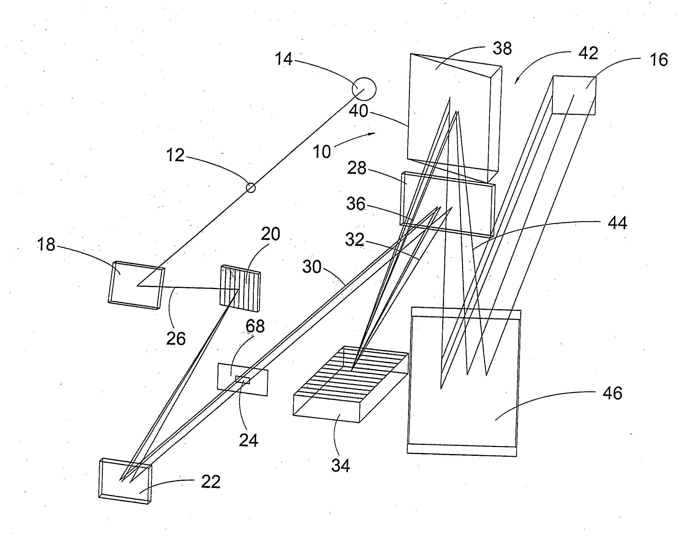
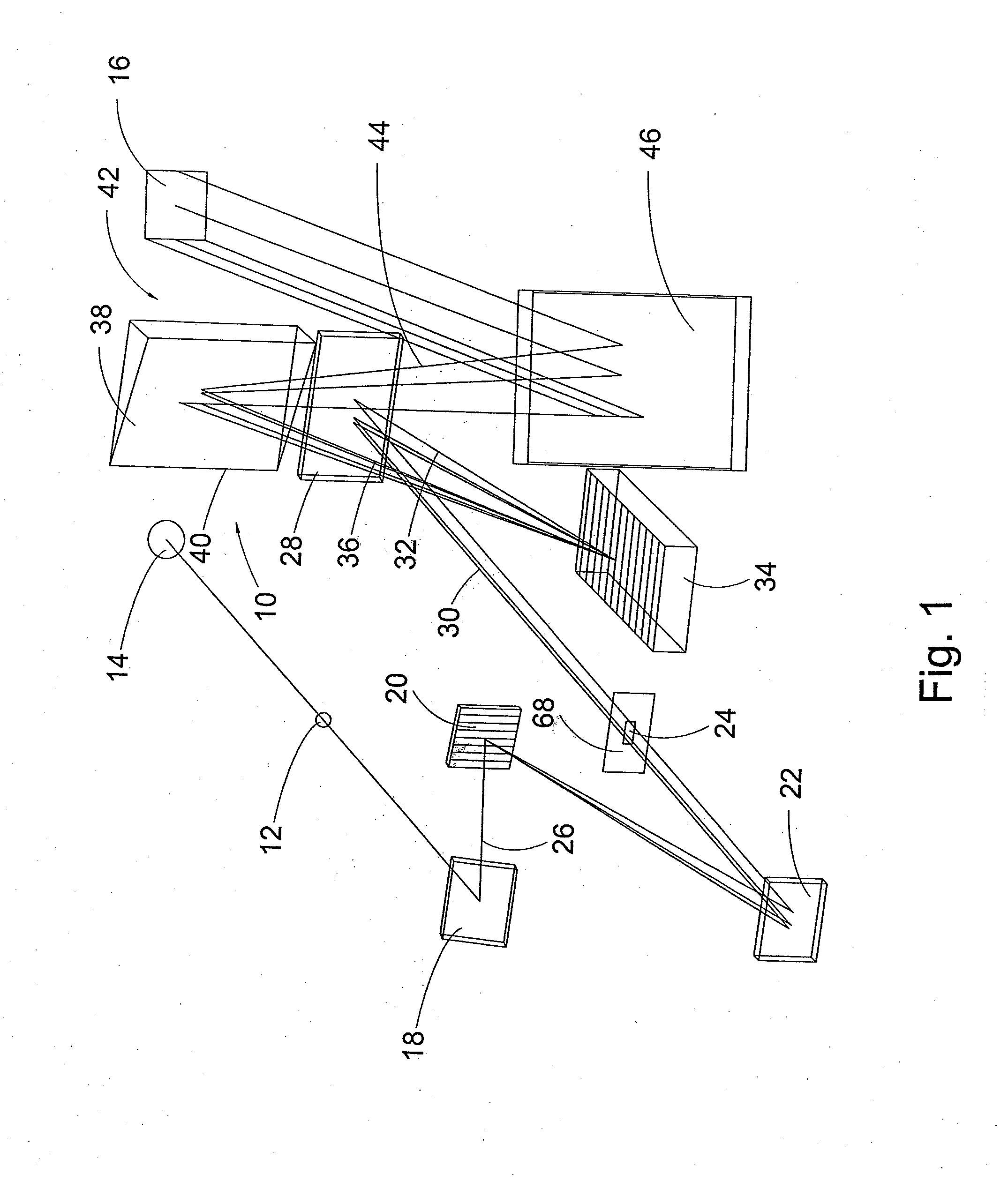
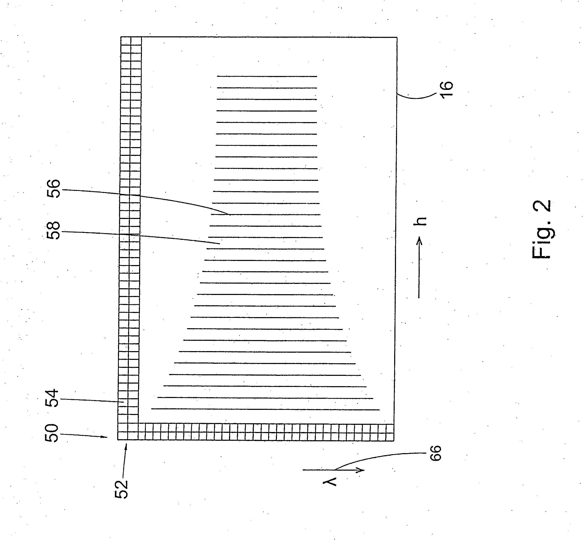
[0024]In a further modification of the invention, the predispersing element is a grating. Preferably, the dispersing element is a prism and the grating line number of the predispersing grating is adapted to the dispersion of the prism in such a way that the orders imaged onto the detector appear essentially with even distances. In other words: the predispersed spectrum is manipulated by the selection of the grating line number and the focus of the predispersing imaging optical assembly in such a way that it essentially compensates the distribution resulting from the lateral dispersion and the predispersion and the distribution of the free spectral ranges of the Echelle grating which is proportional to the square of the wavelength. The selection of such suitable optical means results in essentially equidistant spaces between the orders and thereby the optimum use of the detector surface.
[0027]Obviously, the optical means for manipulating the predispersed spectrum can be combined. The predispersion can be effected with a grating in order to enable the use of a small detector and at the same time a greyfilter may be used to account for the dynamic range of the detector. It is important that the additional spectrum provides the possibility of the selective manipulation of the photon number incident on the individual illuminated detector pixel per time unit. Contrary to the use of entirely absorbing blinds or baffles, interim values are possible which are quasi continuously accessible.

Problems solved by technology

Accordingly, high transmission losses occur with a simultaneously small resulting dispersion.

Method used


Image

  • Echelle spectrometer arrangement using internal predispersion
  • Echelle spectrometer arrangement using internal predispersion
  • Echelle spectrometer arrangement using internal predispersion

Examples


Embodiment Construction

[0035]FIG. 1 shows an Echelle spectrometer assembly generally denoted with numeral 10. The Echelle spectrometer assembly 10 is provided with an entrance slit 12. The entrance slit 12 is illuminated by radiation from a radiation source 14. Such a radiation source is, for example, a Xenon short arc high pressure lamp or a deuterium emitter as it is used in atomic absorption spectroscopy. Alternatively, the radiation emitted by an emission source, such as, for example, an inductively coupled plasma (ICP) can be imaged on the entrance slit.

[0036]The width and the height of the entrance slit 12 are adapted to the width and the height of the detector elements of a detector 16. A predispersing imaging optical assembly with a collimator mirror 18 and a camera mirror 22 image the entrance slit 12 to an image plane 24. A plane grating 20 is arranged between the collimator mirror 18 and the camera mirror 22. The plane grating 20 serves to predisperse the incident parallel radiation 26 coming f...


PUM


Abstract

An Echelle spectrometer arrangement (10) with internal order separation contains an Echelle grating (34) and a dispersing element (38) for order separation so that a two-dimensional spectrum having a plurality of separate orders (56) can be generated, an imagine optical system (18, 22, 28, 46), a flat-panel detector (16), and predispersion means (20) for predispersing the radiation into the direction of traverse dispersion of the dispersion element (38). The arrangement is characterized in that the predispersion means (20) comprise a predispersion element which is arranged along the optical path behind the inlet spacing (12) inside the spectrometer arrangement. The imaging optical system is designed in such a manner that the predispersed radiation can be imaged onto an additional image plane (24) which does not have any boundaries in the predispersion direction and which is arranged along the optical path between the predispersion element (20) and the echelle grating (34). Optical means (20, 68) in the area of the predispersed spectrum are arranged to influence the spatial and / or the spectral beam density distribution on the detector (16).

Description

Technical Field[0001]The invention relates to an Echelle spectrometer assembly with internal separation of the orders, comprising[0002](a) an Echelle grating for the spectral separation of radiation in a main dispersion direction,[0003](b) a dispersing element for the separation of the orders by means of the spectral separation of the radiation in a lateral dispersion direction forming an angle with the main dispersion direction of the Echelle grating such that a two-dimensional spectrum with a plurality of separated orders is generated,[0004](c) an imaging optical assembly for imaging the radiation entering into the spectrometer assembly through an entrance slit in an image plane, and[0005](d) a detector having a two-dimensional arrangement of a plurality of detector elements in the image plane, and[0006](e) predispersion means for predispersion of radiation in the direction of the lateral dispersion of the dispersing element.[0007]In an Echelle spectrometer, gratings are used whic...

Claims


Application Information

Patent Timeline
IPC IPC(8): G01J3/40G01J3/443G01J3/42
CPCG01J3/02G01J3/0213G01J2003/1828G01J3/2803G01J3/1809
Inventor BECKER-ROSS, HELMUTFLOREK, STEFANOKRUSS, MICHAEL
Owner LEIBNIZ - INSTITUT FUER ANALYTISCHE WISSENSCHAFTEN ISAS
Learn More