
Method for repairing and strengthening pipe with internal helically wound tensile reinforcement

a tensile reinforcement and pipe technology, applied in the direction of pipes, mechanical equipment, pipes, etc., can solve the problems of buried pipe infrastructure rapidly deteriorating throughout the world, other pressure pipes subject to large internal hydrostatic pressure, and pipes exposed to aggressive environments deteriorating over time, so as to prevent torsional stress accumulation, improve the bonding of the hardening matrix to the substrate of the pipe, and relieve the stress on the tensile reinforcement material

Active Publication Date: 2011-11-17
STRUCTURAL GRP
View PDF11 Cites 7 Cited by
  • Summary
  • Abstract
  • Description
  • Claims
  • Application Information

AI Technical Summary

Benefits of technology

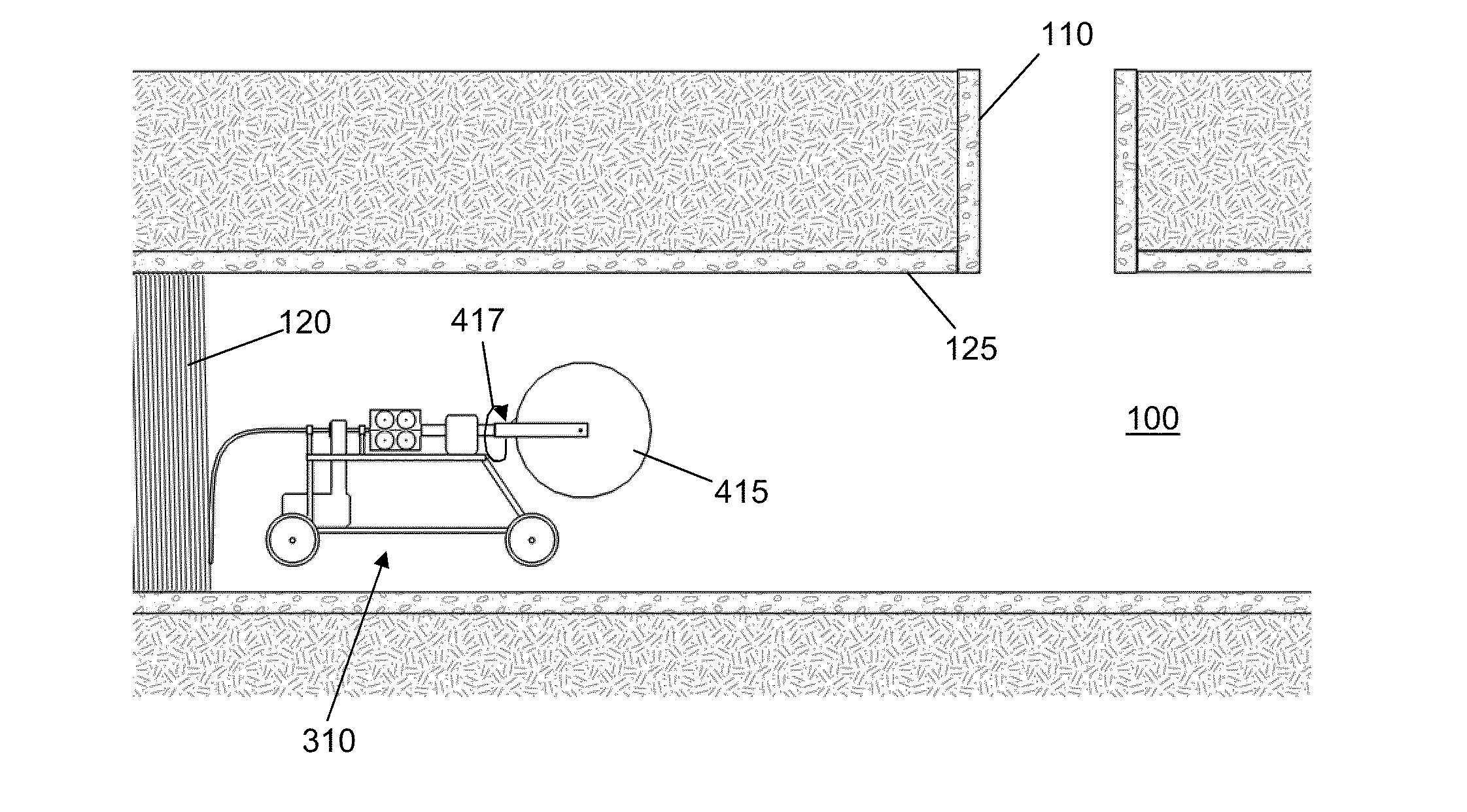
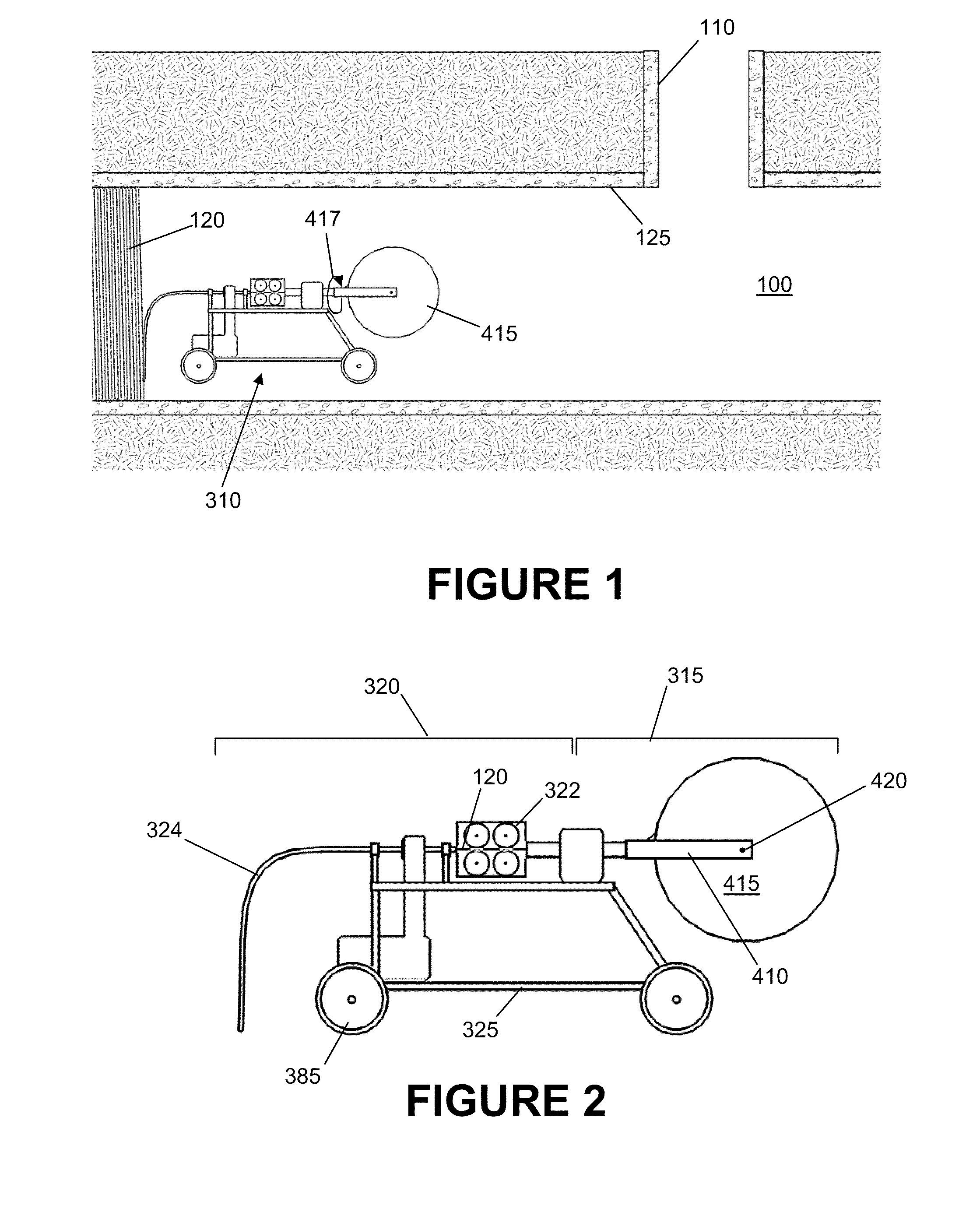
[0007]A method for repairing a pipe is disclosed in which a tensile reinforcement material is pushed into a helical winding against the inside wall of the pipe while avoiding the creation of and / or relieving torsional stress on the tensile reinforcement material that would otherwise be created by the act of winding it around the inside wall of the pipe.
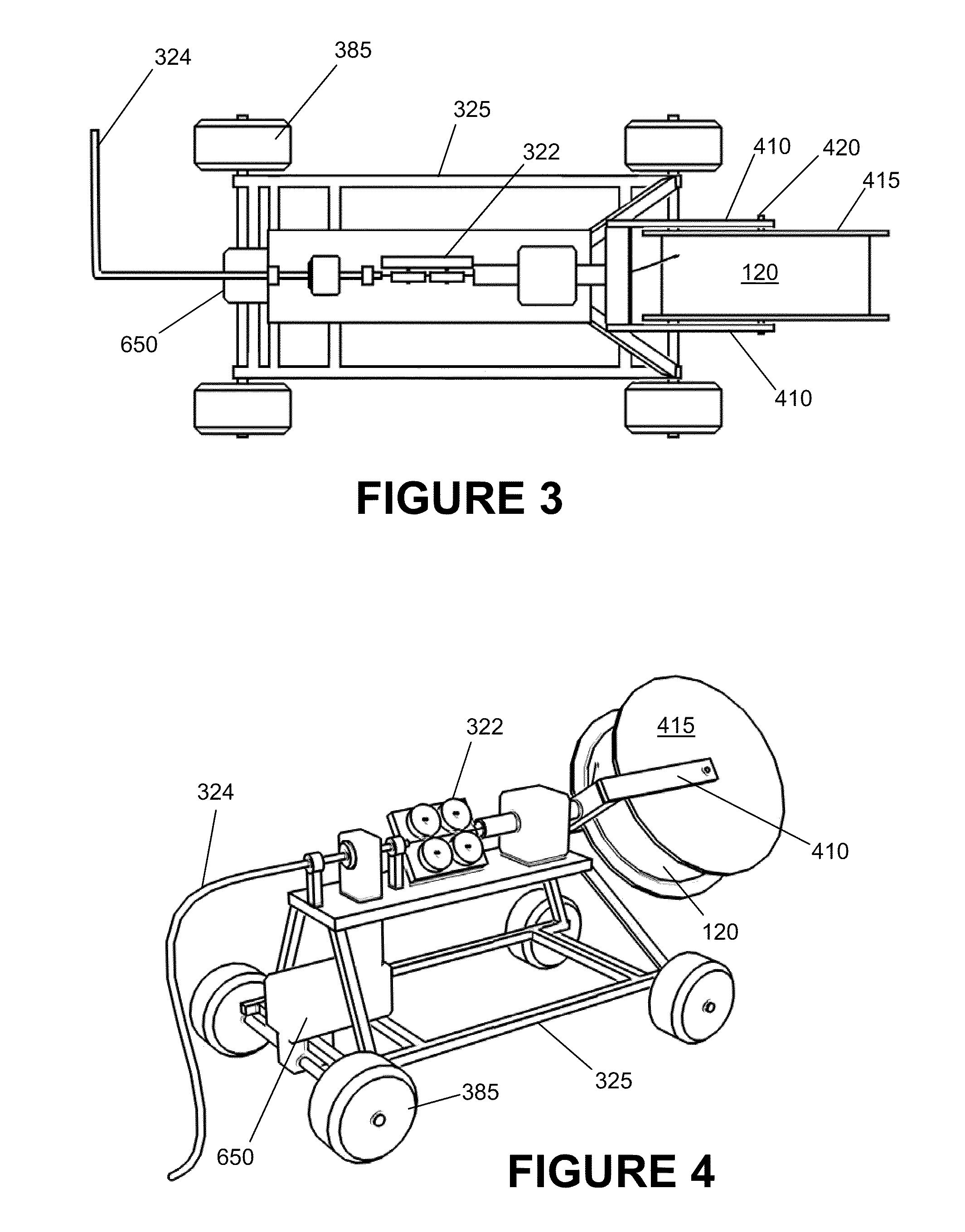
[0009]With regard to certain aspects of the invention, the spool assembly may be connected to and held on the movable cart. As the pusher feeds the tensile reinforcement material from the spool assembly to the installation arm and winds the tensile reinforcement material around the inside wall of the pipe, the spool assembly may be rotated in order to relieve the stress on the tensile reinforcement material as it is being wound around the inside wall of the pipe.
[0010]With regard to other aspects of the invention, the spool assembly may be mounted on a powered turntable, and the system may further comprise a turntable pusher, a continuous rotating sheath rotationally connected to the turntable at one end of the sheath, and a movable cart and installation arm positioned adjacent the opposite end of the sheath. The powered turntable may be placed outside the pipe and feed the tensile reinforcement material to the continuous rotating sheath, while turning in order to prevent the accumulation of torsional stress in the reinforcement material.
[0011]Likewise, with regard to still further aspects of the invention, the spool may be connected to and held on a movable cart within the pipe, and may be configured to only rotate about the spool's axle so as to take off tensile reinforcement material from the spool, with the axle of the spool extending parallel to the length of the pipe. As tensile reinforcement material is taken off from the spool, the reinforcement material is routed through a pusher. The pusher and installation arm are mounted on a support arm that likewise rotates about an axis that is parallel to the length of the pipe, such that as tensile reinforcement material is pushed through the installation arm, it is wound around the inside wall of the pipe. As the tensile reinforcement material is taken off of the spool and pushed through the installation arm, it remains in line with the direction in which it is pushed into successive coils against the interior wall of the pipe, thus preventing torsional stress from accumulating in the tensile reinforcement material that would otherwise be created by the act of winding it around the inside of the pipe.
[0012]In each of the above cases, the helical coil of tensile reinforcement material is embedded within a hardening matrix, which may be finished to provide a smooth interior pipe surface. Moreover, by compressing the tensile reinforcement material into the interior wall of the pipe, the bond of the hardening matrix to the substrate of the pipe is improved, as the process of compressing the tensile reinforcement material into the pipe wall forces the hardening matrix into the pores of the substrate, thus forming a strengthened composite reinforcement inside of the pipe.

Problems solved by technology

Buried pipe infrastructure is rapidly deteriorating throughout the world.
Many pipes transmit water and waste in gravity flow conditions, while other pressurized pipes are subject to large internal hydrostatic pressures.
Pipes exposed to aggressive environments deteriorate over time due to corrosion or other material processes depending upon the materials of which they are constructed.
In the case of pressure pipes, failure can result in expensive and dangerous main breaks.
The reinforcing prestressed wires are subject to deterioration and breakage resulting in pipe failure.
External pressure from the surrounding environment and internal pressure from the water they carry may cause the pipes to crack and leak.
In order to repair the pipes, segments must typically be removed entirely requiring significant disruption to traffic and structures above the pipes, such as roads or buildings.
In addition, such repairs consume significant amounts of time and resources, and can be quite costly.
The currently existing methods of lining or reinforcing pipes are labor intensive and expensive.

Method used


Image

  • Method for repairing and strengthening pipe with internal helically wound tensile reinforcement
  • Method for repairing and strengthening pipe with internal helically wound tensile reinforcement
  • Method for repairing and strengthening pipe with internal helically wound tensile reinforcement

Examples


Embodiment Construction

[0029]The invention summarized above may be better understood by referring to the following description, claims, and accompanying drawings. This description of an embodiment, set out below to enable one to practice an implementation of the invention, is not intended to limit the preferred embodiment, but to serve as a particular example thereof. Those skilled in the art should appreciate that they may readily use the conception and specific embodiments disclosed as a basis for modifying or designing other methods and systems for carrying out the same purposes of the present invention. Those skilled in the art should also realize that such equivalent assemblies do not depart from the spirit and scope of the invention in its broadest form.

[0030]A method for repairing a pipe is described in which a tensile reinforcement material, having sufficient stiffness to resist buckling over short distances, is compressed onto the inside surface of the pipe into a continuous helical coil of vario...


PUM

PropertyMeasurementUnit
lengthaaaaaaaaaa
tensile reinforcementaaaaaaaaaa
torsional stressaaaaaaaaaa

Abstract

A method for repairing and strengthening pipes by creating a structural reinforced composite liner within the existing pipe. The liner is created by helically winding a tensile reinforcement material on the inside wall of a pipe and encapsulating it in a hardening matrix material. The reinforcement material is helically wound around the inside wall of the pipe by an installation device. The installation device is configured to relieve and / or prevent the development of torsional stress in the reinforcement material that is created by the act of helically winding it onto the inside wall of a pipe, allowing the reinforcement material to lay flat against the pipe wall without twisting or buckling. The structural reinforced composite can be configured to supplement the strength of the existing pipe or to function as a stand-alone pipe within the existing pipe.

Description

CROSS-REFERENCE TO RELATED APPLICATION[0001]This application is based upon and claims priority from co-pending U.S. Provisional Patent Application Ser. No. 61 / 395,392 entitled “Novel means of replacing and strengthening pipe with internally wound wire reinforcement and pressure applied concrete,” filed with the United States Patent and Trademark Office on May 13, 2010, by the inventor herein, the specification of which is incorporated herein by reference in its entirety.BACKGROUND OF THE PRIOR ART[0002]1. Field of the Invention[0003]The present invention relates to a method of in-situ strengthening of existing pipes, and more particularly to a method for strengthening pipes by installing a reinforced composite inside the pipe, comprising a helically wound tensile reinforcement material.[0004]2. Background of the Prior Art[0005]Buried pipe infrastructure is rapidly deteriorating throughout the world. Many pipes transmit water and waste in gravity flow conditions, while other pressuri...

Claims


Application Information

Patent Timeline
Patent Type & Authority Applications(United States)
IPC IPC(8): F16L9/00F16L55/18
CPCF16L55/1655B29C53/8075F16L55/18F16L55/1656B29C63/32
Inventor EMMONS, PETER H.CRIGLER, JOHN R.MOUSSA, MICHAEL R.DOCK, DAN A.BAUER, SCOTT V.SAUER, NATHAN D.
Owner STRUCTURAL GRP
Learn More