Electrode for a solar cell, manufacturing method thereof, and solar cell

Inactive Publication Date: 2011-11-10
SSCP CO LTD
View PDF0 Cites 15 Cited by
  • Summary
  • Abstract
  • Description
  • Claims
  • Application Information

AI Technical Summary

Benefits of technology

[0012]In order to solve the above problems, there is provided a method for manufacturing an electrode for a solar cell. In the method, the electrode is printed to have a plurality of layers by a printing method, such as a gravure offset, using conductive pastes. Each of the conductive pastes for each of the layers has a polymer binder with different glass transition temperature and different boiling temperature. Thus, the electrode can have a high aspect ratio and the contact between a substrate and the conductive electrode material can be excellent. There is also provided a solar cell manufactured by the method and having a high cell efficiency.
[0013]In one general aspect, there is provided a method for manufacturing an electrode for a solar cell by a printing method through using a composition for an electrode for a solar cell. The composition includes a polymer binder, a diluting solvent, a metal electrode material, and a glass powder. The method includes printing a composition for an electrode for a solar cell including a low Tg polymer binder as the polymer binder on a substrate to improve a contact property between the substrate and the conductive electrode material; and printing a composition for an electrode for a solar cell including a high Tg polymer binder as the polymer binder to improve an aspect ratio.

Problems solved by technology

A material of the single crystal type has a high efficiency with high property due to a high purity and a low defect density, but the material of the single crystal type is expensive.
In this case, there are several problems, for example, a quality of the line shape is not good, a working property is poor due to clogging of a printing plate caused by the repeated printings, the multi-layer printing is not easy, and an aspect ratio decreases at firing.

Method used


Image

  • Electrode for a solar cell, manufacturing method thereof, and solar cell
  • Electrode for a solar cell, manufacturing method thereof, and solar cell
  • Electrode for a solar cell, manufacturing method thereof, and solar cell

Examples


Embodiment Construction

Example 2Example 3Binder15 (Tg 87° C.)15 (Tg 26° C.)15 (Tg −19° C.)Diluting2.02.02.0solventSlip1.01.01.0Agent ( )Dispersing1.01.01.0AgentSilver787878PowderGlass333PowderTotal 100100 100

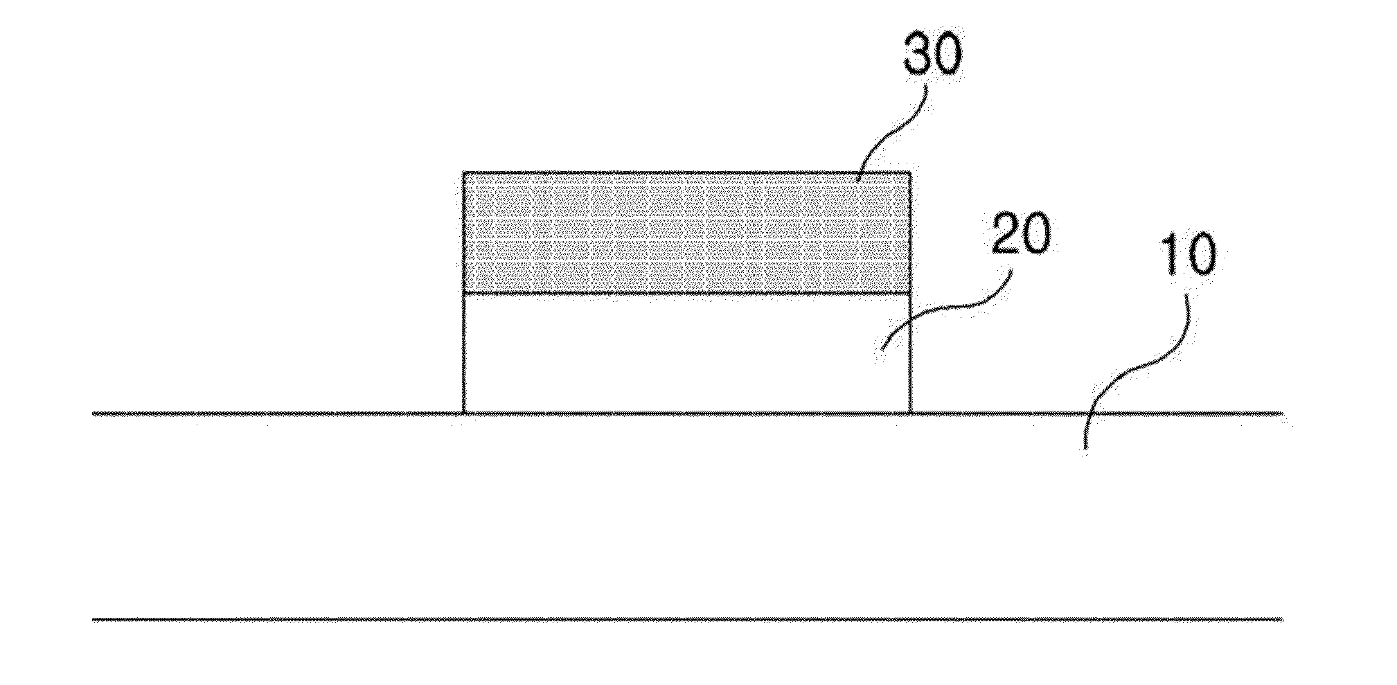
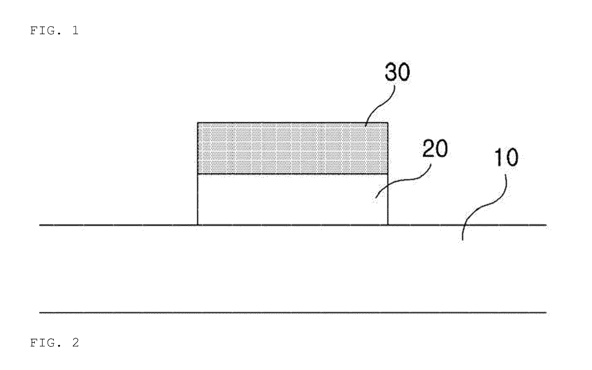
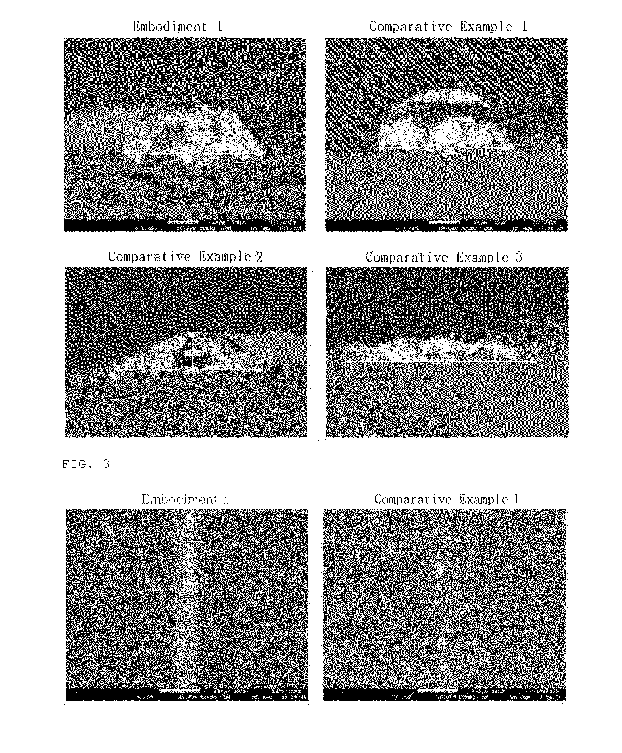
[0070]Also, printing methods in Embodiment 1, and Comparative Examples 1 to 3 are shown in following Table 2, and an aspect ratio, a line width, a height, and a cell efficiency of the electrode are shown Table 3, and FIGS. 2 and 3.

TABLE 2ComparativeComparativeComparativeEmbodiment 1Example 1Example 2Example3A number of printing3333First layer materialManufacturingManufacturingManufacturingManufacturingExample 3Example 1Example 2Example 3Second layer ManufacturingManufacturingManufacturingManufacturingmaterialExample 1Example 1Example 2Example 3Third layer materialManufacturingManufacturingManufacturingManufacturing Example 1Example 1Example 2Example 3

TABLE 3Aspect ratioLine widthEfficiency(height / width)height [μm][μm](%)Embodiment 10.42819.345.118.9%Comparative0.49621.242.7 8.9%Example 1Comparative0.2...


PUM

PropertyMeasurementUnit
Temperatureaaaaaaaaaa
Lengthaaaaaaaaaa

Abstract

There is provided an electrode for a solar cell, in which the electrode is printed using a polymer binder with a low Tg (hereinafter, referred to as a low Tg polymer binder) to improve a contact property between a substrate such as silicon wafer, or the like, and a conductive electrode material, and subsequently, using a polymer binder with a high Tg (hereinafter, referred to as a high Tg polymer binder) to improve the aspect ratio. The printed electrode is fired, thereby obtaining the electrode with a high aspect ratio, an improved contact property between the substrate and the conductive electrode material, and an enhanced cell efficiency. There is also provided a manufacturing method thereof and a solar cell.

Description

CROSS REFERENCE TO RELATED APPLICATION(S)[0001]This application is a continuation of International Patent Application No. PCT / KR2009007555, filed on Dec. 17, 2009, which claims the benefit of Korean Patent Application No. 10-2008-0128511 filed on Dec. 17, 2008, the entire disclosures of which are incorporated herein by reference for all purposes.BACKGROUND[0002]1. Field[0003]The following description relates to an electrode for a solar cell, a method for manufacturing the same, and a solar cell.[0004]2. Description of Related Art[0005]A solar cell is a semiconductor device for converting solar energy to an electric energy. The solar cell may have a p-n junction, and the fundamental structure thereof is the same as a diode. When a light is incident into the solar cell, the incident light is absorbed to the solar cell and is interacted with a material constituting the semiconductor of the solar cell. As a result, electrons and holes as minority carriers are formed, and they drift to c...

Claims


Application Information

Patent Timeline
IPC IPC(8): H01L31/0224H01L31/18
CPCH01B1/16H01L31/022425Y02E10/50H05K3/245H05K1/095H01B1/22H01L31/04H01L31/18
Inventor DAN, CHEOL HOJUN, TAE HYUNSONG, HA CHUL
Owner SSCP CO LTD
Why Eureka
Try Eureka