Vibration-type force detection sensor and vibration-type force detection device

Inactive Publication Date: 2011-10-27
SEIKO EPSON CORP
View PDF12 Cites 2 Cited by
  • Summary
  • Abstract
  • Description
  • Claims
  • Application Information

AI Technical Summary

Benefits of technology

[0012]An advantage of some aspects of the invention is to provide a vibration-type force detection sensor and a vibration-type force detection device which have a simple configuration, a short response time (measurement time) of the force detection, low power consumption, and low cost.Application Example 1

Problems solved by technology

However, the acceleration sensor unit disclosed in JP-A-2009-271029 is a sensor of a frequency changing type, and while there is an advantage in that there is a lower level of noise due to the digital output, it is necessary that the frequency is counted in the width of gate time and there are problems in that the response time is slow and the current consumption is large.
In addition, a master clock is necessary for counting the frequency and there is a drawback in that the acceleration detection device becomes large.
In addition, since the sensitivity of a double tuning fork-type crystal resonator element depends on the width of the vibration arm, there is a problem in that electrode formation becomes difficult when the size is reduced.
In addition, in the capacitance-type acceleration sensor disclosed in JP-A-2010-32538, there is precision processing using photolithography technology, etching technology, and the like, and there is a problem with the yield ratio and there is a problem in that it is easy to have influence from an electric field or static electricity.

Method used


Image

  • Vibration-type force detection sensor and vibration-type force detection device
  • Vibration-type force detection sensor and vibration-type force detection device
  • Vibration-type force detection sensor and vibration-type force detection device

Examples


first embodiment

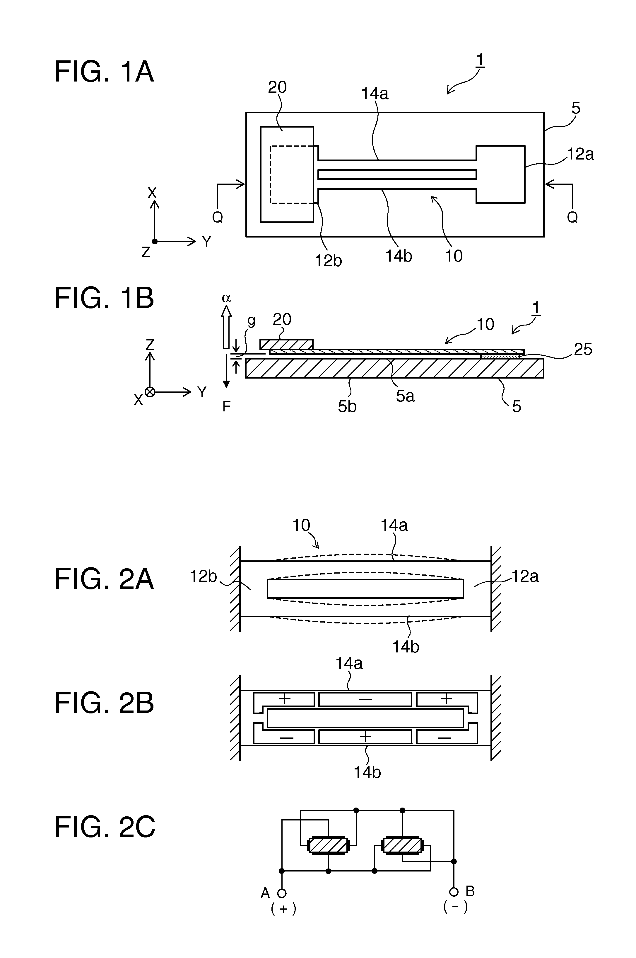
[0039]Below, embodiments of the invention will be described in detail based on the diagrams. FIG. 1A is a schematic planar diagram illustrating a configuration of a vibration-type force detection sensor 1 according to the invention, and FIG. 1B is a cross-sectional diagram along a line Q-Q. The vibration-type force detection sensor 1 is a vibration-type force detection sensor provided with a piezoelectric substrate formed from a quartz crystal substrate or the like, a piezoelectric resonator element 10 where a metallic electrode film is formed on at least one main surface of the piezoelectric substrate, abase 5 which supports the piezoelectric resonator element 10 in a cantilever manner and does not move when a force is added, and a mass portion 20 which is mounted on a free edge portion of the piezoelectric resonator element 10.

[0040]The base 5 is a rectangular substrate formed using glass, quartz crystal, or the like, and both of the main surfaces are parallel to each other.

[0041]...

second embodiment

[0065]FIGS. 8A and 8B are diagrams illustrating a configuration of a vibration-type force detection sensor 2 where FIG. 8A is a planar diagram and FIG. 8B is a cross-sectional diagram along a line Q-Q. The vibration-type force detection sensor 2 is provided with a piezoelectric substrate, piezoelectric resonator elements 10a (10b) where a metallic electrode film is formed on at least one main surface of the piezoelectric substrate, a base 5 which supports the piezoelectric resonator elements 10a (10b) in a cantilever manner and does not move when a force is added, and mass portions 20a (20b) which are each mounted on free edge portions of the piezoelectric resonator elements 10a (10b).

[0066]The piezoelectric substrate is provided with vibration portions 14a and 14b (14c and 14d) and support portions 12a and 12b (12c and 12d) which support each of both end portions of the vibration portions 14a and 14b (14c and 14d). In addition, the mass portions 20a (20b) are each mounted on one o...


PUM


Abstract

A vibration-type force detection sensor includes: a piezoelectric resonator element provided with a vibration portion and a support portion connected to one end of the vibration portion; and a base which is provided with one main surface which is connected to the support portion and the piezoelectric resonator element is arranged, wherein the piezoelectric resonator element is in a state where the other end side of the vibration portion can oscillate so that the size of a gap between the vibration portion and the one main surface changes when a force acts in a direction which is orthogonal with the one main surface of the base, and is supported in parallel with the one main surface of the base so that an electric equivalent resistance of the vibration portion changes according to the change in the size of the gap.

Description

BACKGROUND[0001]1. Technical Field[0002]The invention relates to a force detection sensor, and in particular to a vibration-type force detection sensor and a vibration-type force detection device which have a simple configuration and a fast response speed.[0003]2. Related Art[0004]From the past, an acceleration sensor which uses a piezoelectric resonator element has been known. The acceleration sensor which uses a piezoelectric resonator element is configured so that, when a force acts in a detection axial direction on the piezoelectric resonator element, the oscillation frequency of the piezoelectric resonator element changes and the acceleration applied to the acceleration sensor is detected from the change in the oscillation frequency.[0005]In JP-A-2009-271029, an acceleration sensor unit is disclosed. An acceleration sensor unit 101 is provided with a structural body 105 with a rectangular shape and a stress sensitive element 107 as shown in FIG. 11. The structural body 105 with...

Claims


Application Information

Patent Timeline
IPC IPC(8): G01P15/10G01C19/56G01C19/5614G01C19/5628G01L1/10
CPCG01C19/5656G01P15/097G01L1/183G01L1/165
Inventor SATO, KENTA
Owner SEIKO EPSON CORP
Why Eureka
Try Eureka