
Multi-domain in-plane switching liquid crystal displays

Inactive Publication Date: 2006-11-02
UNIV OF CENT FLORIDA RES FOUND INC
View PDF11 Cites 6 Cited by
  • Summary
  • Abstract
  • Description
  • Claims
  • Application Information

AI Technical Summary

Benefits of technology

[0008] A secondary objective of the invention is to provide the chevron-shaped multi-domain in-plane switching mode liquid crystal display (LCD) having a small color shift.
[0009] A third objective of the invention is to provide the chevron-shaped multi-domain in-plane switching mode LCD having a fast response time.
[0012] The multi-domain in-plane switching liquid crystal display of the present invention includes a first and second substrate, an electrode structure having plural chevron-shaped electrodes, and alignment layers on each substrate. A liquid crystal material is sandwiched between the alignment layers that aligns the liquid crystal material and polarizers are disposed on exterior surfaces of the substrates to provide a multi-domain in-plane switching liquid crystal display with small color shift, wide viewing angle and fast response. The liquid crystal material has either a positive or a negative dielectric anisotropy.

Problems solved by technology

Fast response, high contrast ratio, high transmittance and wide viewing angle without color reversal are the main problems for getting high display quality, which is critical in large size monitors and TV applications.
Unfortunately, the off-axes light leakage of the crossed polarizers at the oblique incident angles deteriorates the wide viewing angle properties of conventional in-plane switching LCDs using the stripe-shaped electrodes.
Moreover, since the LC molecules between the electrodes are uni-directionally orientated, a color-shift phenomenon occurs and degrades the image quality when viewed at large incident angles.
In addition, the response time of a 4-μm in-plane switching liquid crystal cell is slow, approximately 50 ms when a special driving circuit and proper LC material design.
However, the results were not very promising.

Method used


Image

  • Multi-domain in-plane switching liquid crystal displays
  • Multi-domain in-plane switching liquid crystal displays
  • Multi-domain in-plane switching liquid crystal displays

Examples


embodiment 1

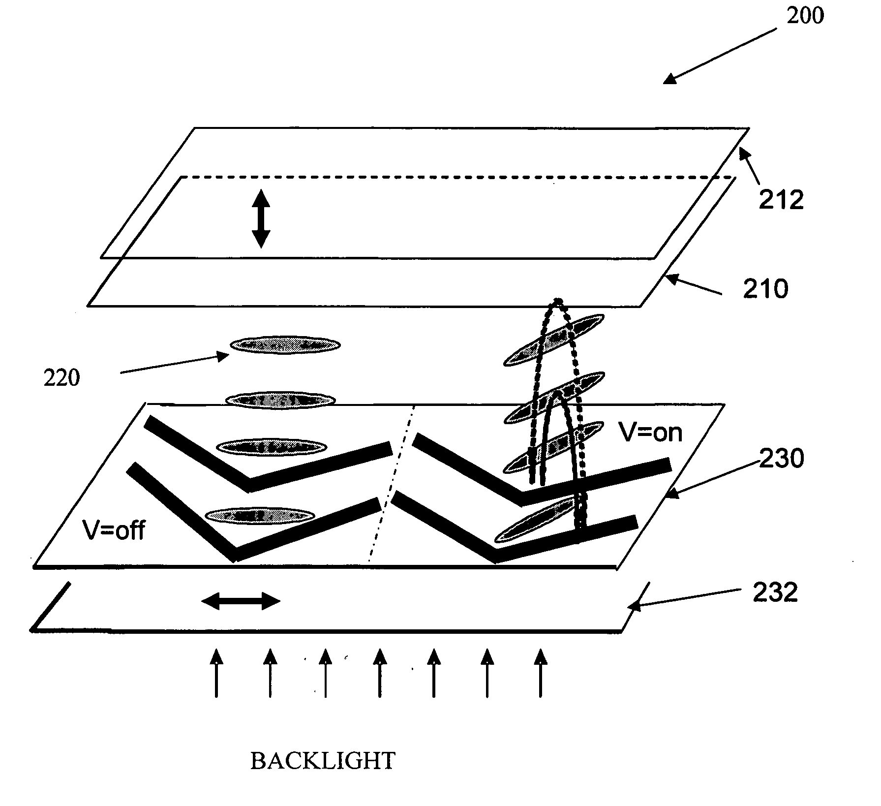
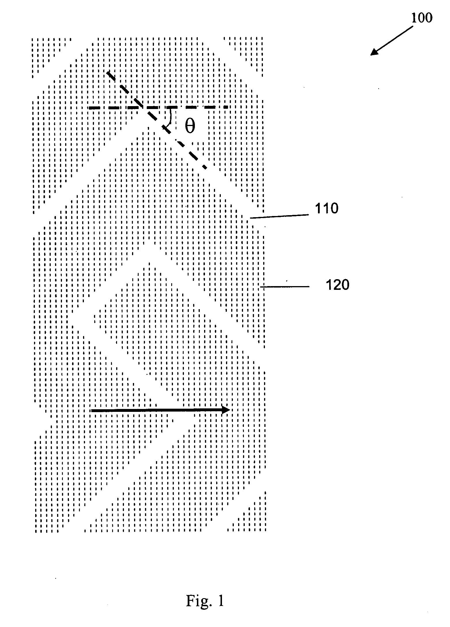
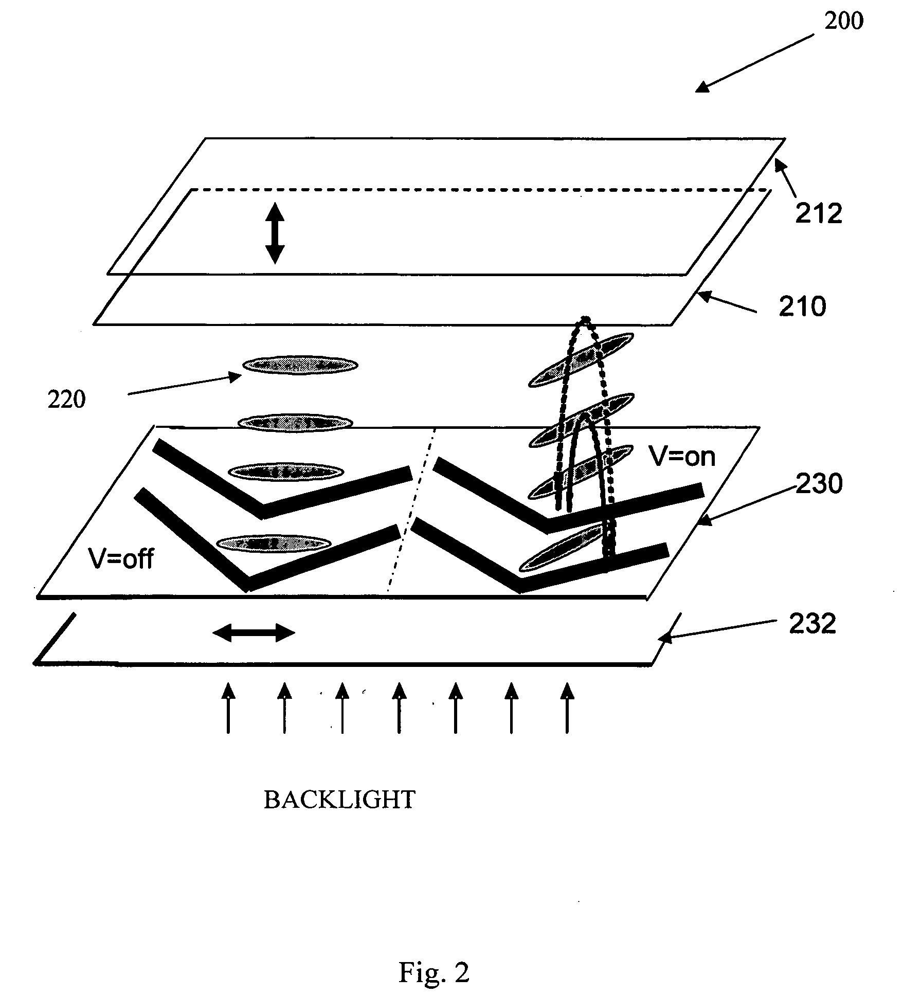
[0058]FIGS. 1 and 2 illustrate the typical chevron-shaped electrode structure and the corresponding device structure and operation when using the homogeneously aligned liquid crystals. The electrode structure 100 consists of the chevron-shaped electrodes in both the horizontal and vertical directions which divides the electrode structure into at least two regions. A series of chevron-shaped electrodes are alternatively arranged to form the inter-digital electrodes on the same substrate as the common electrode 110 and the pixel electrode 120, respectively, which are connected to the thin-film transistors (not shown). The common electrode 110 and the pixel electrode 120 can be formed using the same photolithography process, or prepared respectively and separated by passivation layers such as SiO2. The distance between adjacent common electrodes 110 and pixel electrodes 120 can be larger than the cell gap for in-plane switching or smaller than the cell gap to take advantage of the frin...

embodiment 2

[0066] As previously described, FIG. 3 illustrate a typical chevron-shaped electrode structure and corresponding general device structure of a chevron-shaped multi-domain in-plane-switching LCD using vertically aligned liquid crystals. The electrode structure consists of the chevron-shaped electrodes in the horizontal and vertical directions which divide the electrode structure into at least two regions. A series of chevron-shaped common electrodes and chevron-shaped common electrodes are alternately arranged to form the inter-digital electrodes one of the substrates and are connected to the thin-film transistors. The chevron-shaped common electrode and the chevron-shaped pixel electrode can be formed using the same photolithography process, or prepared respectively and separated by passivation layers such as SiO2. At the boundary between regions, the chevron-shaped common electrodes and the chevron-shaped pixel electrodes occupy adjacent space for the fully transverse switching to ...

embodiment 3

[0072]FIG. 4 is a plan view of a general electrode structure of a chevron-shaped multi-domain in-plane-switching liquid crystal display with two uniformly aligned liquid crystal domains. The electrode structure consists of the chevron-shaped electrodes in both the horizontal and vertical directions which divides the electrode structure into at least two different regions as previously discussed in the first embodiment.

[0073] The electrode structure is divided into two parts with the different liquid crystal aligning directions, which is usually perpendicular to each other and as shown in FIG. 4 where the arrows indicate the LC alignment directions. The two initial aligned LC domains can be obtained by double rubbing method, photo-alignment method or the inkjet printing process. Since the double multi-domain in-plane-switching liquid crystal display can be regarded as two separate in-plane-switching liquid crystal display operating simultaneously, its operational mechanism is simila...


PUM


Abstract

A multi-domain in-plane-switching liquid crystal display with small color shift, wide viewing angle and fast response. The structure of the multi-domain in-plane switching liquid crystal displays comprises plural chevron-shaped common electrodes and chevron-shaped pixel electrodes, arranged alternatingly to form a multi-domain liquid crystal distributions. In an embodiment the structure includes a polarizer and an analyzer and the liquid crystal material is homogenously aligned. In another embodiment the structure includes alignment films for vertically aligning the liquid crystal material and crossed linear polarizers, circular polarizers or a combination of linear polarizers and compensation film. In another embodiment, the multi-domain in-plane switching liquid crystal display provides at least two different uniformly aligned liquid crystal domains, for a double multi-domain-In-plane switching LC display.

Description

[0001] This invention relates to the structure of in-plane switching liquid crystal displays, and more specifically to the structure of a liquid crystal display with chevron-shaped electrodes that form the multi-domain liquid crystal distributions with small color shift, wide viewing angle and fast response. BACKGROUND AND PRIOR ART [0002] Liquid crystal displays (LCDs) have been widely used in the mobile displays, notebook computer panels, personal computer (PC) monitors and TVs. Fast response, high contrast ratio, high transmittance and wide viewing angle without color reversal are the main problems for getting high display quality, which is critical in large size monitors and TV applications. As one of the promising candidates, in-plane switching (IPS) mode liquid crystal display has been introduced for getting the high display quality in these areas because of its inherent wide viewing angle properties as described in S. Yeo, A LC Display for TV Application, SID 2004 Digest, (20...

Claims


Application Information

Patent Timeline
IPC IPC(8): G02F1/1337
CPCG02F1/134363G02F1/133753
Inventor LU, RUIBOWU, SHIN-TSONHONG, QI
Owner UNIV OF CENT FLORIDA RES FOUND INC
Learn More