
Optochemical sensor active element, method of its preparation and use

Active Publication Date: 2011-10-06
AGILENT TECH INC
View PDF2 Cites 5 Cited by
  • Summary
  • Abstract
  • Description
  • Claims
  • Application Information

AI Technical Summary

Benefits of technology

[0014]In a preferred embodiment of the invention, the photoluminescent indicator dye is an O2 sensitive dye, and wherein the polymeric material has moderate permeability to O2. Typically, the polymeric material is selected from the group consisting of: high density

Problems solved by technology

However, the need for sensor support leads to a problem of adhesion of sensor composite to it.
Strong interaction between the two materials is not desirable as this may lead to the formation of mixed phases and / or regions of heterogeneity, thus affecting sensing properties.
Common matrices used in O2 sensors (hydrophobic polymers such as polystyrene) are not very compatible with support materials such as glass or other polymers (e.g. polyethylene and polypropylene widely used in packaging).
The use of such complex cocktails containing polymer and volatile solvents complicates production of sensors and imposes certain restrictions.
Thus, viscous and volatile formulations are difficult to handle, manipulate and dispense in small volumes, they tend to dry during casting procedure or printing.
Also thin film coatings are fragile, tend to degrade with time, delaminate and fall off, especially from hydrophobic and flexible support materials.
Although traditional sensor design and fabrication techniques produce satisfactory sensors, they are relatively complex from the fabrication point of view and not very suitable for certain applications where high accuracy and reproducibility of measurements is required (e.g. with disposable or calibration free sensors).
Complex composition and fabrication of the current O2 sensors, non-optimal physical-chemical and sensing properties, limited applicability and analytical performance and relatively high production costs limit their use.
Incorporation of such sensors in sample vessels or packages made of inert materials is also difficult and requires additional steps and components (e.g. adhesive).

Method used


Image

  • Optochemical sensor active element, method of its preparation and use
  • Optochemical sensor active element, method of its preparation and use
  • Optochemical sensor active element, method of its preparation and use

Examples


example 1

Impregnation of solvent-crazed polymers with O2-sensitive dyes and fabrication of O2 sensors

[0065]Using hand-operating clamps, strips of HDPE film with gage dimensions of 50×20 mm and thickness of 60 microns were stretched in hexane along the direction of melt-extrusion by a tensile strain of 175%, and allowed to dry under a stream of air while remaining stretched. A solution of PtOEPK dye in hexane (1.0 mg / ml) was applied dropwise on the surface of hexane-crazed HDPE matrix with a pipette and allowed to dry under fixed dimensions in air for 10 min. The resulting polymers stained with the dye (thickness of ˜40 microns) produced the phosphorescent material which can be used for sensing of O2.

[0066]Using hand-operating clamps, strips of HDPE with gage dimensions of 15×100 mm and thickness of 25 microns were stretched in hexane along the direction of melt-extrusion by a tensile strain of 120% and allowed to dry under a stream of air. This solvent-crazed HDPE matrix was submerged in a ...

example 2

Preparation of O2 sensors in a continuous process

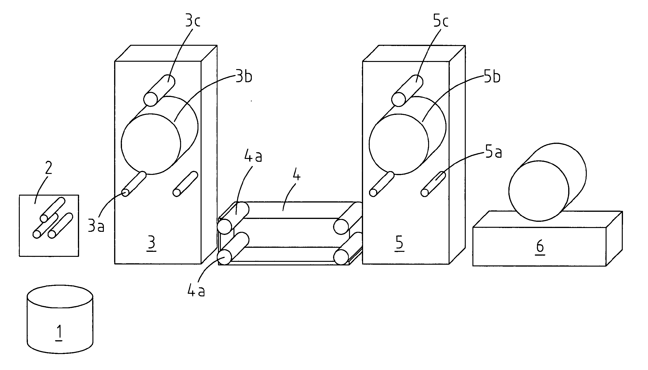
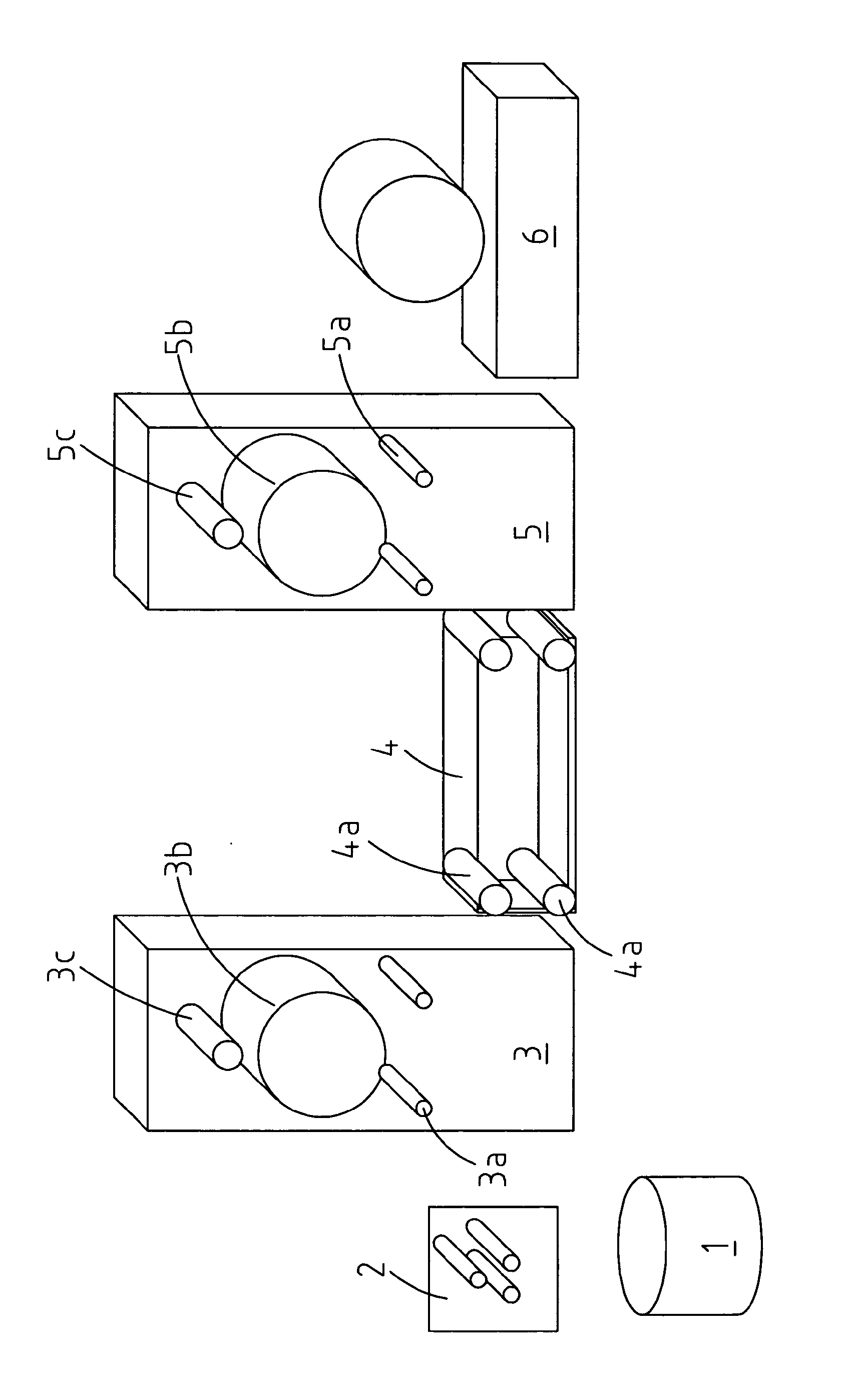
[0071]A computer-controlled set-up was constructed which serves to orient polymer films and fibers in a precise and controlled way and to provide continuous stretching and solvent crazing of polymer tape. It involved feed rolls, a guide roll, a solvent bath, take-off rolls, and a winder. A general sketch is shown in FIG. 1 in which 1 is the roll of the initial polymer film (may be a non-oriented or slightly oriented film, 2 indicates the film guiding rolls, 3 indicates the film feeding module with two guiding rolls 3a, a feeding roll rotating at a pre-set speed 3b, and a film aligning roll 3c, 4 indicates a crazing bath with active solvent and a set of four guiding rolls 4a, 5 indicates a receiver module with two guiding rolls 5a, a receiving roll rotating at pre-set speed 5b, and a guiding roll for folding the polymer tape 5c, and 6 indicates a module for winding the processed film into rolls. Polymer film 1 having width 10-50 mm, th...

example 3

Properties of O2 sensors based on solvent-crazed polymers

[0079]O2 sensors based solvent-crazed HDPE and PP polymers, produced according to the procedures described in Examples 1,2, were investigated for their photophysical and sensing properties. For all the polymers, relatively high degree of impregnation with the dyes was achieved. Thus, the PtOEPK-HDPE sensors produced from a 25 micron thick tape according to Example 2 showed absorbance values typically ranging between 0.02-0.2 at 586 nm (absorption maximum for PtOEPK), after their heat-treatment and sealing of the nanopores. Phosphorescent signals were comparable to those of traditional sensors.

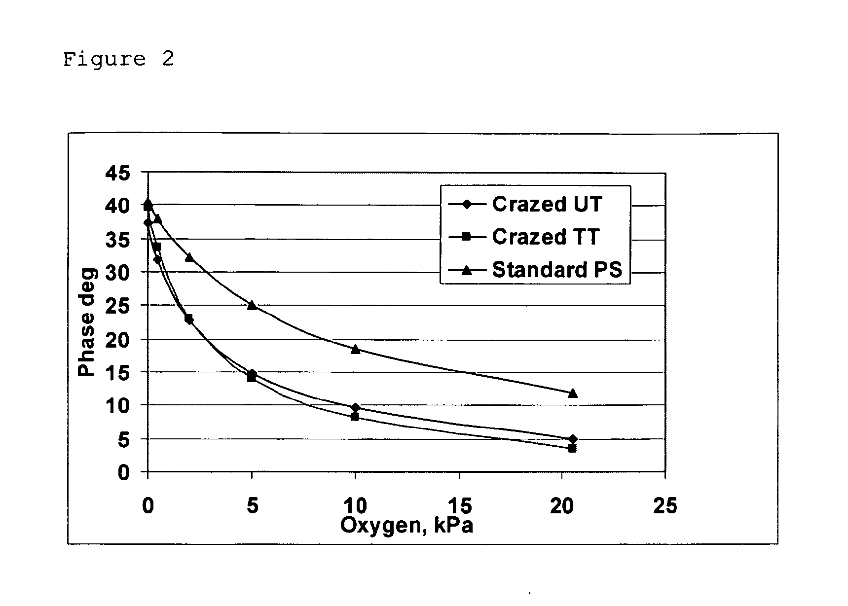
[0080]Phosphorescence signals obtained from the sensors were high enough to measure O2 in the gaseous and aquesous samples by phase-fluorometry. Measurements performed with a bench-top phase-fluorometric detector described in (Papkovsky D B et al[0081]Analytical Letters, 2000, v.33(9), 1755-1777) produced the following calibrations for th...


PUM

PropertyMeasurementUnit
Pore sizeaaaaaaaaaa
Thicknessaaaaaaaaaa
Fractionaaaaaaaaaa

Abstract

An optochemical sensor element suitable for sensing an analyte comprises a polymeric material in which at least a portion of the polymer material is solvent crazed to provide a multiplicity of pores of controlled nanometer size, and an indicator dye impregnated into the pores, in which optochemical sensor element the indicator dye is a long-decay photoluminescent dye selected from the group consisting of: phosphorescent platinum(II)—and palladium (II) complexes of porphyrin dyes such as octaethylporphine, coproporphyrin, octaethylporphine -ketone, benzoporphine, tetra (pentafluorophenyl) porphine, chlorin e6; fluorescent complexes of ruthenium (II), osmium(II), iridium(III) and europium (III); or derivatives or close analogs of these dyes. The sensor element in the presence of the analyte alters a photoluminescence parameter thus allowing sensing and / or quantification of the analyte.

Description

FIELD OF THE INVENTION[0001]The invention relates to material chemistry, sensors, (bio) analytical and detection systems, particularly to indicator-mediated sensors based on optical detection. The invention can be used in biotechnology, chemical and electronic industry, environmental and biomedical applications, process control, packaging of foods, biopharmaceuticals, electronic components and in other areas where measurement of molecular oxygen (O2) and other physical and chemical parameters is required.BACKGROUND OF THE INVENTION[0002]Over the past decades numerous optochemical sensors and biosensors have been developed for the measurement and continuous monitoring of important physical, chemical and biological parameters. Corresponding sensing materials often rely on indicator dyes incorporated in polymeric matrices, which provide means for qualitative or quantitative assessment of analyte(s) of interest by measuring sensor optical properties. Such materials are routinely used fo...

Claims


Application Information

Patent Timeline
IPC IPC(8): G01N21/00C09K11/06C09K11/02B65D77/00B05D5/06
CPCG01N21/643G01N31/225B01D67/0023G01N31/22G01N21/78G01N2021/7786
Inventor ARZHAKOVA, OLGA VLADIMIROVNA
Owner AGILENT TECH INC
Learn More