Motor and electric device using same
- Summary
- Abstract
- Description
- Claims
- Application Information
AI Technical Summary
Benefits of technology
Problems solved by technology
Method used
Image
Examples
embodiment 1
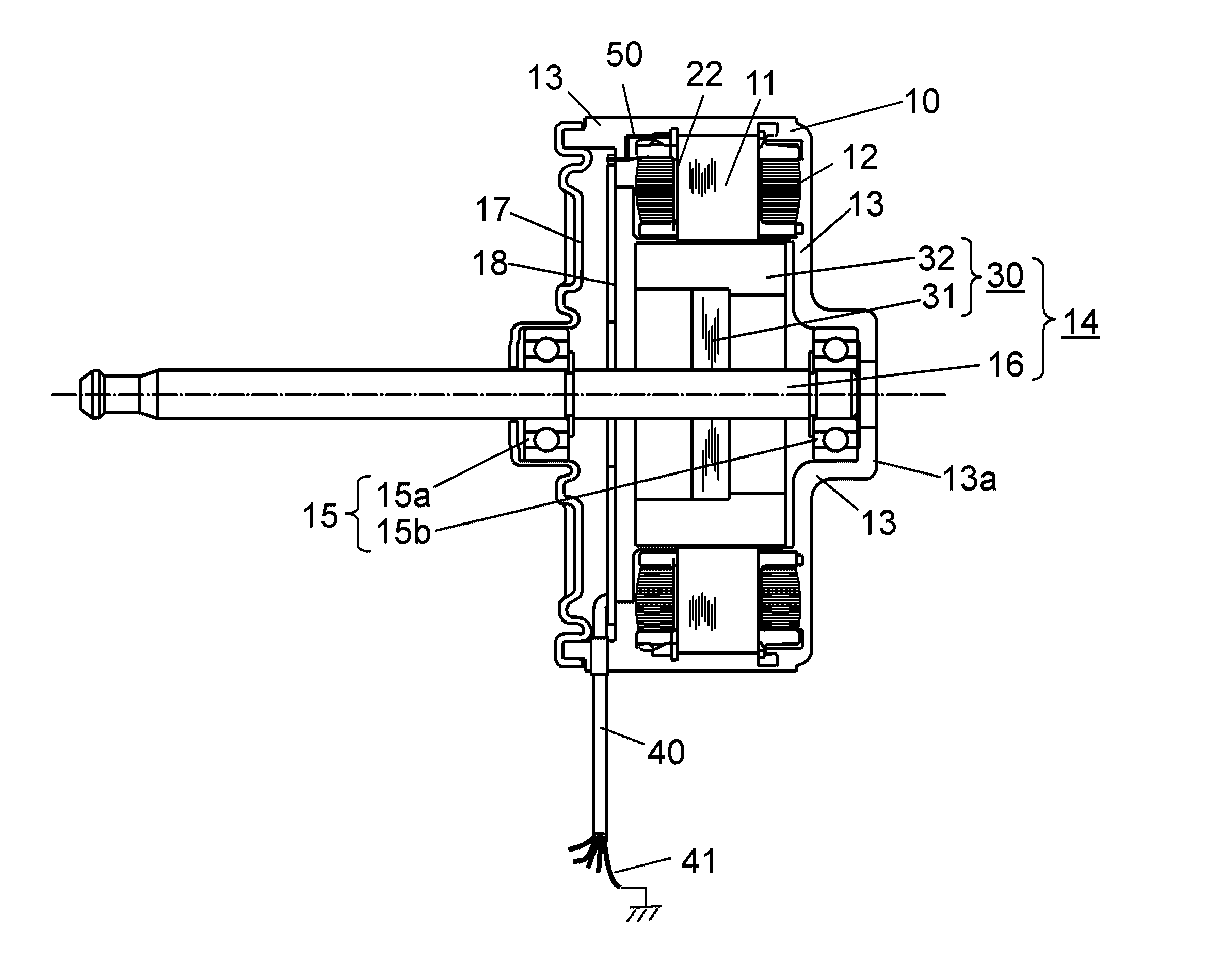
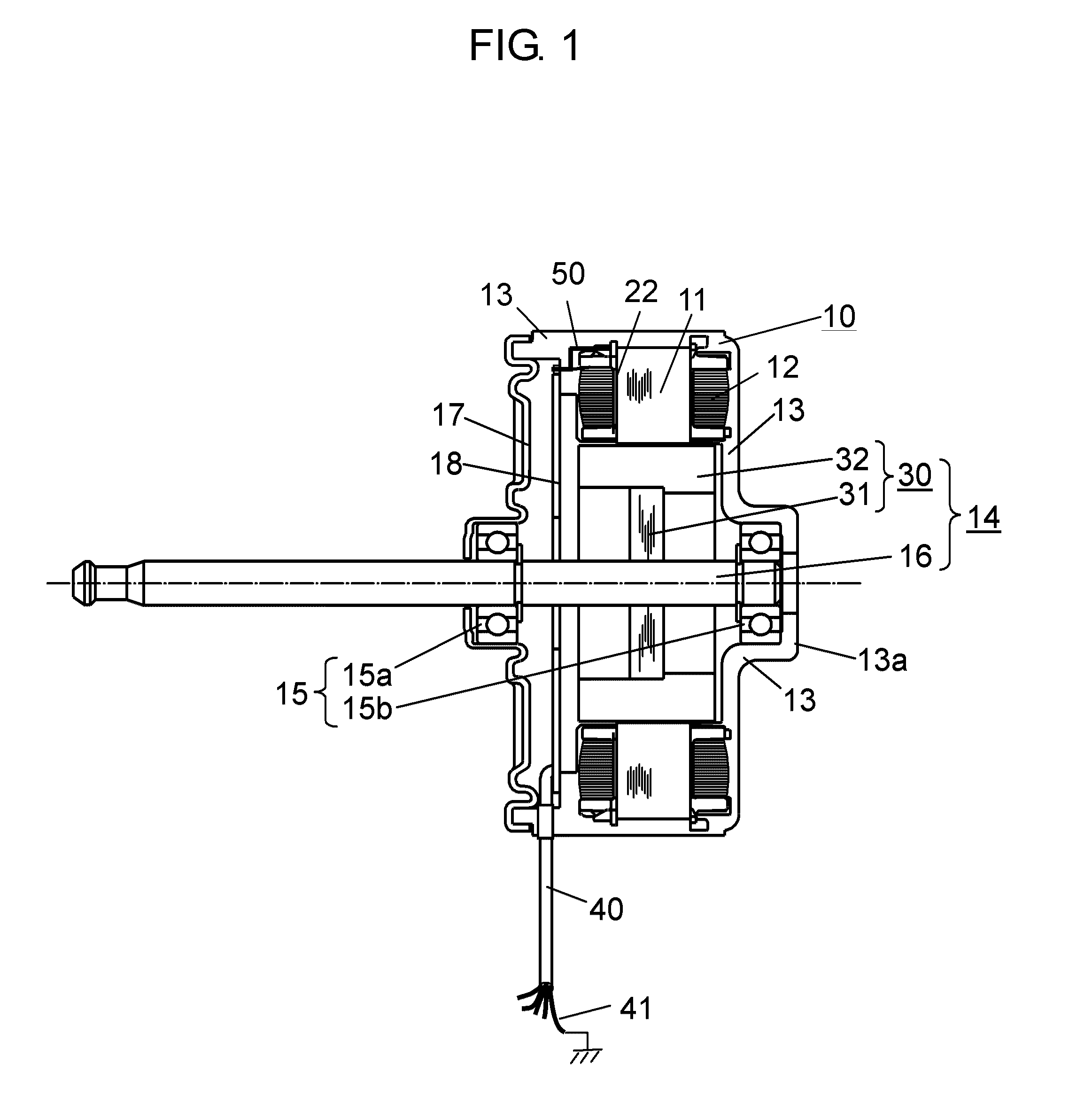
[0024]FIG. 1 is a structural diagram showing a cross section of a motor according to Embodiment 1 of the present invention. In the present embodiment, an example of a motor that is a brushless motor to drive a blowing fan in an indoor unit mounted for an air conditioner serving as an electric device will be described. In the present embodiment, an example of an inner rotor type motor in which a rotor is rotatably arranged on an inner circumference side of a stator will be described.
[0025]In FIG. 1, on stator iron core 11, stator winding 12 serving as a winding is wound on insulator 22 serving as a resin that insulates stator iron core 11. Stator iron core 11 is molded together with another fixing member with insulating resin 13 serving as a molding material. In the present embodiment, the members are integrally molded in such a manner to configure stator 10 having a generally cylindrical shape as an outer shape.
[0026]Inside stator 10, rotor 14 is inserted via a gap (not shown). Roto...
example 1
[0048]In the example, a shaft voltage obtained when stator iron core 11 of the brushless motor shown in FIG. 1 was connected to the ground line of drive circuit substrate 18 through conductive member 50 was measured. As a bearing, 608 available from Minebea Co., Ltd. (grease having a consistency of 239 was used) was used.
[0049]FIG. 3 is a diagram showing a method of measuring a shaft voltage in the present example. A DC stabilized power supply was used in a shaft voltage measuring state. The measurement was executed under the same operating conditions in which power supply voltage Vdc of the winding was set to 391 V, power supply voltage Vcc of the drive circuit was set to 15 V, and a rotating speed was set to 1000 r / min. The rotating speed was adjusted by control voltage Vsp, and an attitude of the brushless motor in an operating state was set to make the shaft horizontal.
[0050]In the measurement of the shaft voltage, voltage waveforms were observed with digital oscilloscope 130 (D...
embodiment 2
[0057]FIG. 4 is a diagram showing a configuration of a drive circuit substrate built in a motor in Embodiment 2 of the present invention. Also on drive circuit substrate 18 shown in FIG. 4, as in drive circuit substrate 18 according to Embodiment 1, various electronic parts (not shown) are mounted, and the electronic parts are electrically connected to each other by a wiring pattern pattern-formed with a copper foil on drive circuit substrate 18. The motor according to the present embodiment has the same configuration as that of the brushless motor having the structure shown in FIG. 1, and a detailed description of the motor will be omitted.
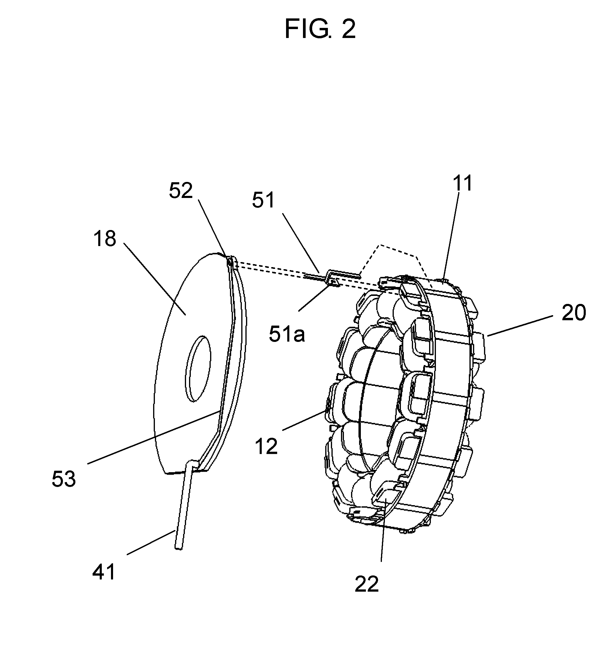
[0058]In comparison with Embodiment 1, the brushless motor according to the present embodiment has a characteristic feature in that stator iron core 11 is electrically connected to ground wiring 41 serving as a reference point of a zero potential through iron core connection terminal 51 serving as a conductive member and further capacitor 60. Mor...
PUM
 Abstract
Description
Claims
Application Information
 - R&D
- Intellectual Property
- Life Sciences
- Materials
- Tech Scout
- Unparalleled Data Quality
- Higher Quality Content
- 60% Fewer Hallucinations
Browse by: Latest US Patents, China's latest patents, Technical Efficacy Thesaurus, Application Domain, Technology Topic, Popular Technical Reports.
© 2025 PatSnap. All rights reserved.Legal|Privacy policy|Modern Slavery Act Transparency Statement|Sitemap|About US| Contact US: help@patsnap.com


