Scroll Compressor

a compressor and roller technology, applied in the direction of machines/engines, rotary/oscillating piston pump components, liquid fuel engines, etc., can solve the problems of motor driving the compressor, electrolytic corrosion occurring in bearings, and easy electrolytic corrosion in bearings, so as to reduce the voltage of the shaft and save spa

Active Publication Date: 2019-10-31
HITACHI IND EQUIP SYST CO LTD
View PDF0 Cites 0 Cited by
  • Summary
  • Abstract
  • Description
  • Claims
  • Application Information

AI Technical Summary

Benefits of technology

[0009]According to the present invention, it is possible to realize the scroll compressor capable of reducing a shaft voltage and achieving space savings.

Problems solved by technology

The motor driving the compressor has a problem such as electrolytic corrosion occurring in bearings.
For example, if the motor operates from an inverter power supply at variable speeds, electrolytic corrosion tends to easily occur in the bearings due to a shaft voltage occurring in the rotary shaft.

Method used


Image

  • Scroll Compressor
  • Scroll Compressor
  • Scroll Compressor

Examples


example

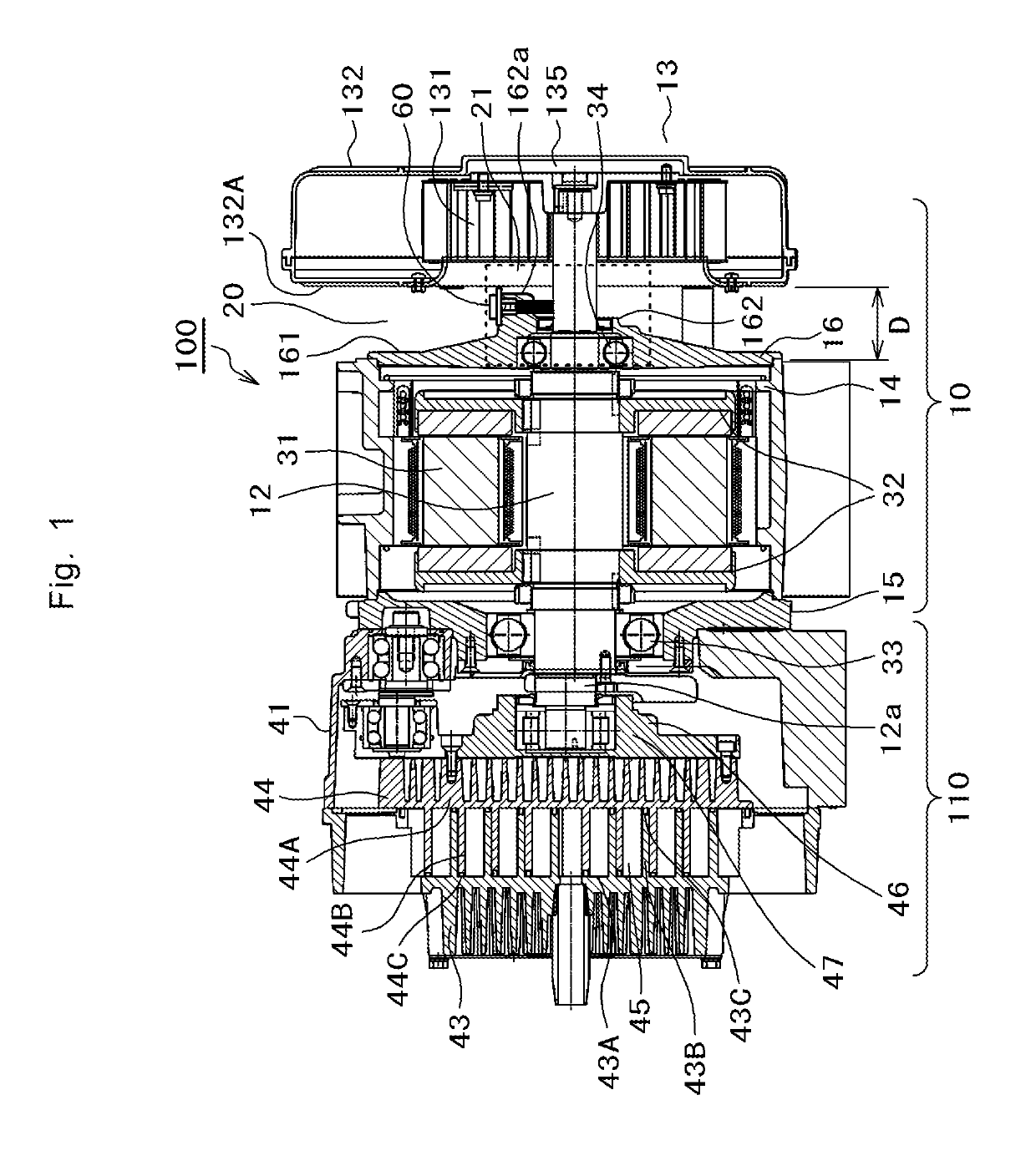
[0013]FIG. 1 is a lateral cross-sectional view of a scroll compressor 100 in an example. The scroll compressor 100 has a motor 10, and a compression portion 110 driven by the motor 10. Hereinbelow, an example of a configuration of an axial gap type motor applied as the motor 10 will be described.

[0014]A stator 31 having a disk shape is disposed in a motor casing 14 of the motor 10, and is interposed between a pair of rotors 32 having a disk shape. The motor casing 14 is made of metal such as Al, and has a cylindrical shape having openings at both ends. A flange 15 made of metal is provided in one opening of the motor casing 14, one opening being located adjacent to the compression portion 110, and an end bracket 16 made of metal is provided in the other opening opposite to one opening. Both openings are sealed.

[0015]A rotary shaft 12 is provided passing through central portions of the stator 31 and the rotors 32. The rotary shaft 12 is rotatably supported by a main bearing 33 provid...


PUM


Abstract

Provided is a scroll compressor capable of reducing a shaft voltage and achieving space savings for the entire apparatus. A scroll compressor 100 includes a rotor 32 that is stored in a motor casing 14; a stator 31 that is stored in the motor casing 14, and drives the rotor 32 to rotate; a rotary shaft 12 that is held by bearings 33 and 34, and rotates integrally with the rotor 32; an end bracket 16 through which one end portion of the rotary shaft 12 passes, and which seals the motor casing 14; an orbiting scroll 44 that supports the other end portion of the rotary shaft 12, and orbits as the rotary shaft 12 rotates; a fixed scroll 43 that is disposed facing the orbiting scroll 44; a suction type cooling fan 13 which is fixed to one end portion of the rotary shaft 12 while being apart by a clearance from the end bracket 16, and which suctions outside air through a suction port provided in an end surface 132A of a fan cover 132, and generates cooling wind for cooling the fixed scroll 43 or the orbiting scroll 44 in the fan cover 132, as a rotary vane 131 accommodated in the fan cover 132 rotates; and a discharge brush 60 which is fixed to the end bracket 16 facing the cooling fan 13, and one end of which is in contact with the rotary shaft 12.

Description

TECHNICAL FIELD[0001]The present invention relates to a scroll compressor.BACKGROUND ART[0002]In the related art, a scroll type compressor integrated with a motor is widely used. In the scroll type compressor integrated with a motor, generally, a cooling fan is mounted on a rotary shaft of a motor to cool a compression portion which becomes very hot during operation.[0003]The motor driving the compressor has a problem such as electrolytic corrosion occurring in bearings. For example, if the motor operates from an inverter power supply at variable speeds, electrolytic corrosion tends to easily occur in the bearings due to a shaft voltage occurring in the rotary shaft. Since undesirable incidents such as shortening the life of the bearings occur due to electrolytic corrosion occurring in the bearings, it is required to reduce the shaft voltage of the motor so as to prevent such incidents.[0004]For example, Patent Document 1 discloses an axial gap type permanent-magnet synchronous moto...

Claims


Application Information

Patent Timeline
Patent Type & Authority Applications(United States)
IPC IPC(8): H02K5/16F04C18/02F04C29/04H02K5/15H02K7/04H02K7/08H02K9/06H02K11/40H02K21/24F16C17/02
CPCF16C17/02H02K11/40F16C2380/26F04C18/0215H02K5/15H02K7/083H02K9/06H02K21/24F04C29/04H02K7/04H02K5/161F16C41/002F04C2280/04F05C2253/06H02K7/14H02K16/02H02K5/1732H02K5/148H02K1/2798F04C2270/165F04C2270/105F04C2240/807
Inventor KATO, FUMINORIKANEMOTO, YOSHIYUKI
Owner HITACHI IND EQUIP SYST CO LTD
Why Eureka
Try Eureka