
Thermal Protection for Disc Brake Components

a technology of disc brake components and thermal protection, which is applied in the direction of bellows, mechanical devices, couplings, etc., can solve the problems of undetectable high amount of heat transfer to heat-sensitive components, large amount of heat passing, and generation of very high temperatures

Active Publication Date: 2011-09-29
BENDIKS SPAJSER FAUNDEJSHN BREJK LLK
View PDF21 Cites 17 Cited by
  • Summary
  • Abstract
  • Description
  • Claims
  • Application Information

AI Technical Summary

Benefits of technology

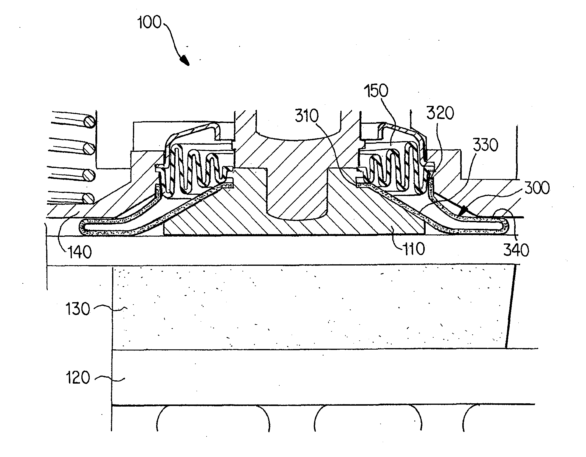
[0013]The present invention addresses the foregoing problems by the novel arrangement of thermal barriers between the bellows and the tappet. In a first embodiment of the present invention, a layer of flexible thermal insulation material is provided between the bellows and the tappet. The layer of flexible thermal insulation material is configured to protect an outer surface of the bellows facing the brake pad from exposure to heat.

Problems solved by technology

The application of a brake pad against a rotating brake disc results in the generation of very high temperatures.
Although a large portion of the heat generated by the friction between the brake pad and the brake disc is dissipated by heat transfer directly from the brake disc to the air, a significant amount of heat passes from the brake pad into the structure of the brake caliper.
In particular, undesirably high amounts of heat may be transferred to heat-sensitive components within the brake caliper.
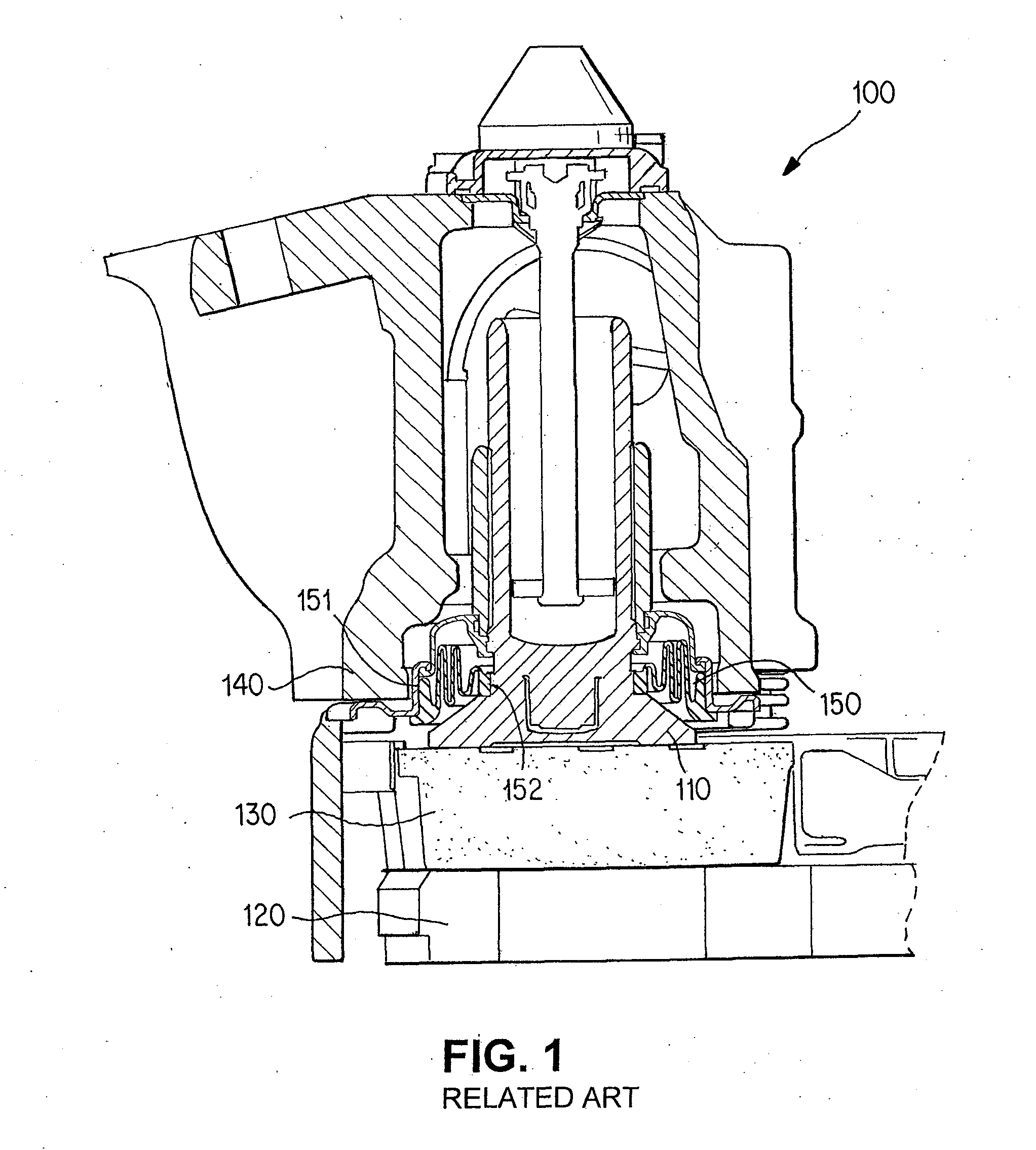
The bellows 150 is also vulnerable to convective heat transfer from the braking process.
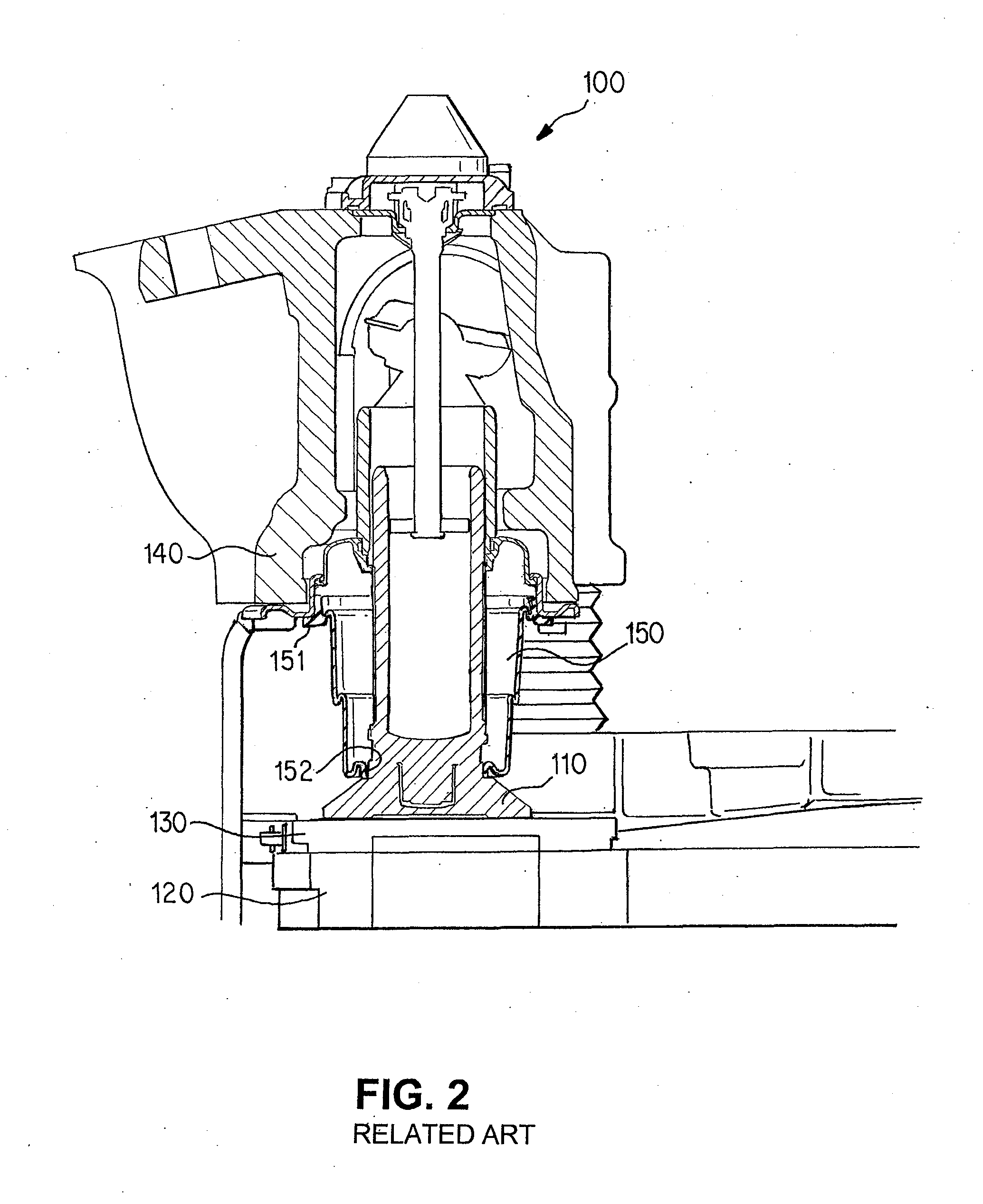
Therefore, the bellows 150 is particularly vulnerable to thermal degradation when the tappet 110 is in the fully extended position.
However, because the metal has a high heat conductivity, the metal may melt or damage the rubber bellows upon contact.
Further, it is difficult to prevent contact between the metallic enclosure and the bellows, due to the small packaging space and the uncontrollable deformation of the bellows and the metallic spring.
In addition, the metallic enclosure has a poor strength of shape, especially along the lateral direction and in the fully expanded position.
This can cause individual coils to skip or jam, which adversely affects the protection function of the metallic enclosure.
It can also compromise the full release of the brake and cause a running clearance reduction with the risk of a hot running brake.
Further, in this state it is not possible to completely retract the tappet from the brake disc to change the brake pad, due to the increased block height of the spiral spring.
However, this requires a high cost for caliper design changes, because metallic bellows are made of very thin-walled and high-grade stainless steel, and the metallic bellows are costly.
In addition, relatively high forces are needed to deform the metallic bellows during extension and retraction of the tappet.
However, this provides limited protection against convective heat transfer, because the sides of the bellows are still exposed.
Also, additional space is needed for the pressure plate and heat shield, and there is a significant additional cost to provide the pressure plate and heat shield, and their connection to the tappet.
The insulation disc is only effective against conductive heat transfer, and does not prevent contact between the bellows and the tappet.
Also, depending on its elasticity, the insulation disc may increase the stroke demand of the brake.
However, none of these disc brake designs provides a heat shield that protects the entire exposed surface of the bellows throughout the operation of the disc brake.

Method used


Image

  • Thermal Protection for Disc Brake Components
  • Thermal Protection for Disc Brake Components
  • Thermal Protection for Disc Brake Components

Examples


Embodiment Construction

[0032]FIG. 3 shows a partial sectional view of a disc brake 100 with an insulation disc 200 between the tappet 110 and the bellows 150, according to an exemplary embodiment of the present invention. Similar to FIG. 1, the tappet 110 shown in FIG. 3 is in a fully retracted position. The insulation disc 200 is inserted into an existing air gap between the tappet 110 and the bellows 150 to prevent the bellows 150 from contacting the tappet 110. The insulation disc 200 has an annular shape. A first end 210 of the insulation disc 200 may be a circular inner circumference that is attached to the tappet 110. A second end 220 of the insulation disc 200 may be a circular outer circumference that extends beyond the outer circumference of the bellows 150. The insulation disc 200 may rest on the tappet 110 and move downward with the tappet 110 to prevent the bellows 150 from contacting the tappet 110. The second end 220 of the insulation disc 200 is not attached to the caliper 140.

[0033]The ins...


PUM


Abstract

A disc brake for a motor vehicle is provided. The disc brake includes a brake disc, a brake caliper configured to straddle the brake disc, a tappet carried by the brake caliper and arranged to push a brake pad against the brake disc, and a bellows provided between the brake caliper and the tappet to seal a gap between the brake caliper and the tappet. A layer of flexible thermal insulation material may be provided between the bellows and the tappet. The layer of flexible thermal insulation material is configured to protect an outer surface of the bellows facing the brake pad from exposure to heat. Alternatively, the bellows may include a layer of flexible thermal insulation material on which an elastomer layer is formed. The layer of flexible thermal insulation material is configured to face the brake pad.

Description

BACKGROUND OF THE INVENTION[0001]The present invention relates to thermal protection of disc brake components.[0002]The application of a brake pad against a rotating brake disc results in the generation of very high temperatures. Although a large portion of the heat generated by the friction between the brake pad and the brake disc is dissipated by heat transfer directly from the brake disc to the air, a significant amount of heat passes from the brake pad into the structure of the brake caliper. In particular, undesirably high amounts of heat may be transferred to heat-sensitive components within the brake caliper.[0003]As shown in FIG. 1, a typical disc brake 100 uses at least one moveable piston or tappet 110 to exert a braking force on a brake disc 120 via a brake pad 130. The disc brake 100 may include two brake pads 130 opposed to each other on either side of the brake disc 120 (not shown). The brake caliper 140 straddles the brake disc 120, with the brake pad 130 located betw...

Claims


Application Information

Patent Timeline
Patent Type & Authority Applications(United States)
IPC IPC(8): F16D65/78F16D3/84
CPCF16D65/18F16J3/043F16D2125/70F16D2065/785H03F3/608
Inventor SIEBKE, ALF
Owner BENDIKS SPAJSER FAUNDEJSHN BREJK LLK
Learn More