Solid-state image sensing device
a sensing device and solid-state technology, applied in the direction of radio frequency controlled devices, instruments, color signal processing circuits, etc., can solve the problems of difficult to divide the signal into signals, difficult to improve image quality, and non-uniformity in the dark
- Summary
- Abstract
- Description
- Claims
- Application Information
AI Technical Summary
Benefits of technology
Problems solved by technology
Method used
Image
Examples
first embodiment
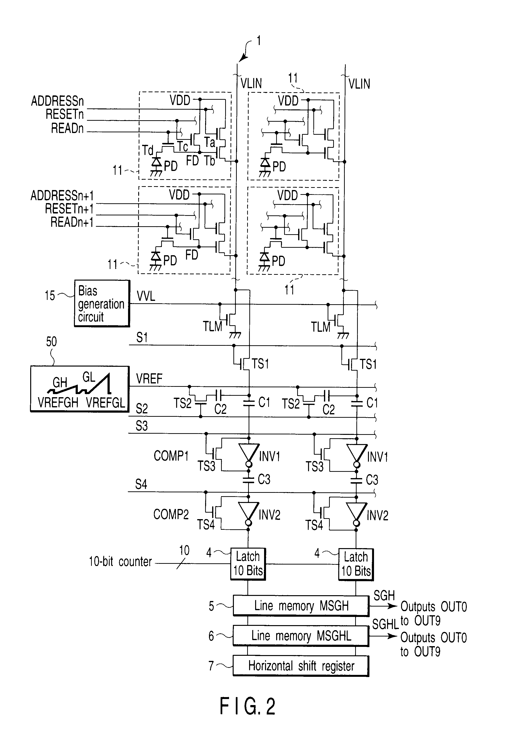
[0045]FIG. 1 is a block diagram showing the schematic arrangement of an amplifier type CMOS image sensor in order to explain a method of widening the dynamic range at low illuminance according to the present invention. A sensor core A comprises a pixel section 1, a column type noise canceling circuit (CDS) 2, a column type analog-to-digital converter (ADC) 3, a latch circuit 4, two line memories (MSGH and MSGHL) 5 and 6, and a horizontal shift register 7.
[0046]The pixel section 1 receives light via a lens 10, and generates charges corresponding to the incident light quantity by photoelectric conversion. In the pixel section 1, cells (pixels) 11 are two-dimensionally arrayed in rows and columns on a semiconductor substrate. One cell 11 has four transistors Ta, Tb, Tc, and Td and a photodiode PD. Each cell 11 receives pulse signals ADDRESSn, RESETn, and READn. Underneath the pixel section 1, load transistors TLM for a source follower circuit are arranged along the horizontal direction...
second embodiment
[0072]FIG. 8 is a block diagram showing the schematic arrangement of an amplifier type CMOS image sensor in order to explain a method of widening the dynamic range at low illuminance according to the present invention. In FIG. 8, the same reference numerals as those in FIG. 1 denote the same parts.
[0073]In FIG. 8, unlike FIG. 1, the former VREF amplitude of a VREF circuit 50 is set to the same gradient GL as that of the latter one. In a sensor core A, a column amplifier AMP 16 is interposed between a vertical signal line VLIN and a switch S1. The GAIN is multiplied by four in the first half of the horizontal scan period, and by one in the second half. This arrangement can reduce the noise mixing amount after the switch S1 to 1 / GAIN. The column amplifier AMP 16 may be an inverter AMP for the source follower. The column amplifier AMP 16 may be of an inversion type. In this case, for example, the waveform VREF needs to be inverted. A timing generator 40 supplies a signal to a pulse amp...
third embodiment
[0076]FIG. 11 is a block diagram showing the schematic arrangement of an amplifier type CMOS image sensor in order to explain a method of widening the dynamic range at low illuminance according to the present invention. In FIG. 11, the same reference numerals as those in FIG. 1 denote the same parts.
[0077]In FIG. 11, unlike FIG. 1, the latter VREFGL waveform of a VREF circuit 50 is set to the same gradient GH as that of VREFGH. A signal obtained by VREFGL is stored in a line memory MSGHL 6, and output as a signal SGHL from a sensor core A. A WDM circuit 20 adds signals SA and SB from which the black level (dark) is simply subtracted, and halves the signal level. Thus, the number of bits does not increase, and the signal SF becomes a 10-bit signal. Further, similar to FIG. 1, random noise can be reduced by 3 dB. If the WDM circuit 20 does not halve the signal level, an 11-bit signal SF is generated. The signal read timing is as shown in FIG. 3 or 4.
PUM
 Abstract
Description
Claims
Application Information
 - R&D
- Intellectual Property
- Life Sciences
- Materials
- Tech Scout
- Unparalleled Data Quality
- Higher Quality Content
- 60% Fewer Hallucinations
Browse by: Latest US Patents, China's latest patents, Technical Efficacy Thesaurus, Application Domain, Technology Topic, Popular Technical Reports.
© 2025 PatSnap. All rights reserved.Legal|Privacy policy|Modern Slavery Act Transparency Statement|Sitemap|About US| Contact US: help@patsnap.com


