Heat Sink, Cooling Module And Coolable Electronic Board

a technology of electronic board and heat sink, which is applied in the direction of lighting and heating apparatus, modifications by conduction heat transfer, and semiconductor/solid-state device details, etc. it can solve the problems of reducing the thermal flux in the direction of the thickness of the base, reducing the durability and reliability of the heat sink itself, and increasing the performance and reliability. , to achieve the effect of reducing the temperature gradient in the base and fins, reducing the heat flux qx in the interior of the bas

Inactive Publication Date: 2011-09-08
KAGOSHIMA UNIV +1
View PDF14 Cites 17 Cited by
  • Summary
  • Abstract
  • Description
  • Claims
  • Application Information

AI Technical Summary

Benefits of technology

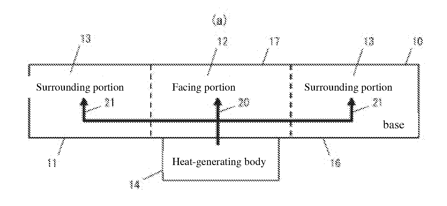
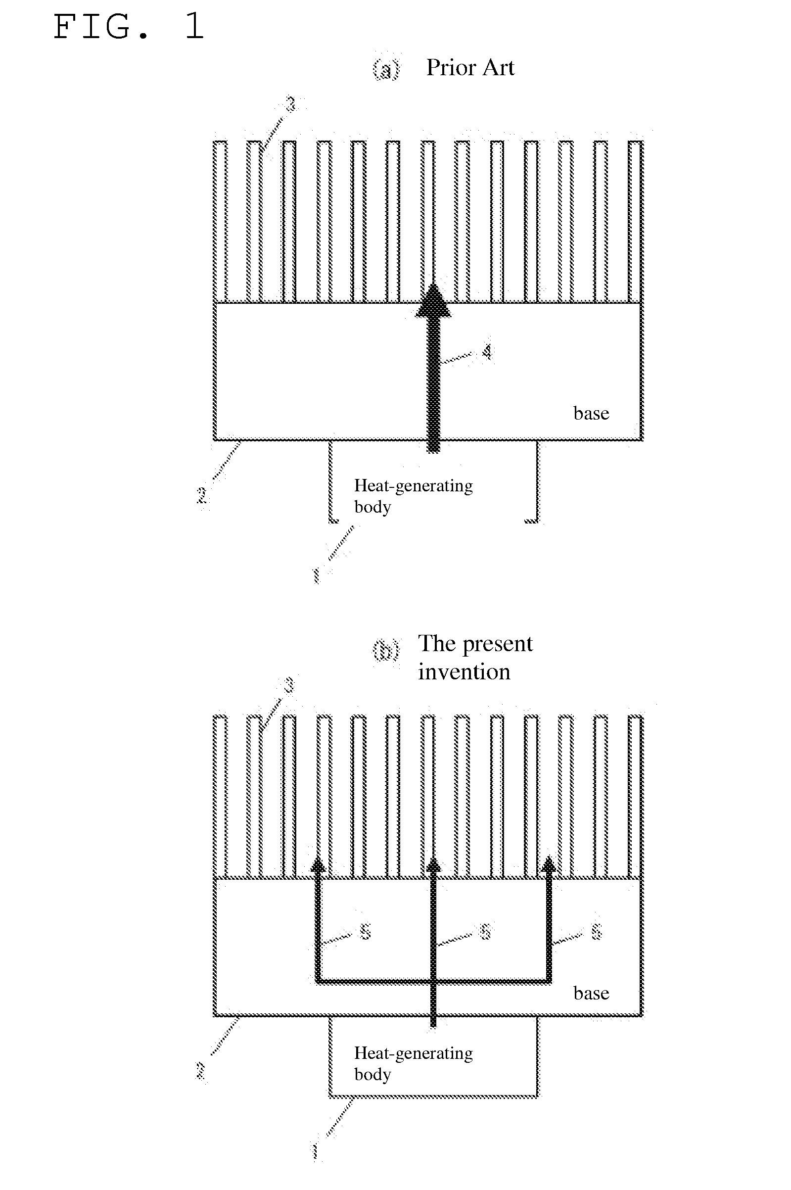
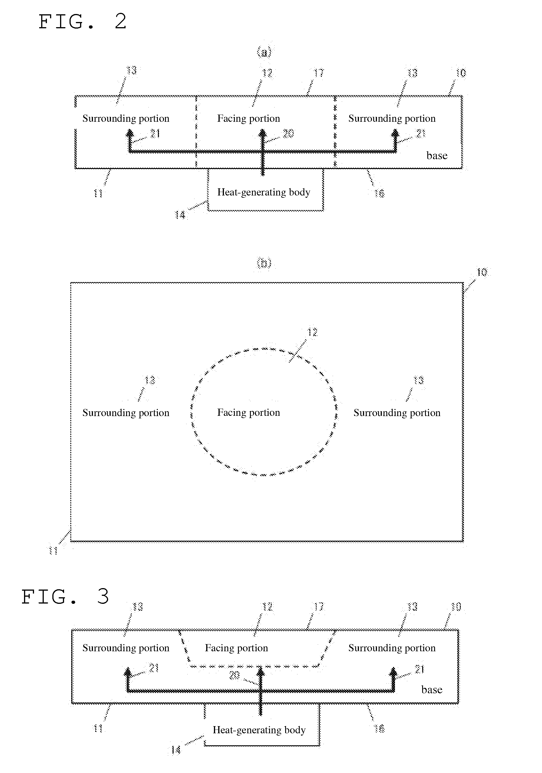
[0018]The references above illustrate the problems (1) in that decreasing the thermal flux in the direction of the thickness of the base is impeded, and (2) at the same time the durability and reliability of the heat sink itself is lost. To solve these problems, the Present application provides a heat sink, a cooling module and a coolable electronic board that, by effectively decreasing the temperature gradient in the base without losing durability or reliability, reduces temperature increases in the heat-generating body (or namely, increases the efficiency of cooling of the heat-generating body). Accordingly, the heat sink of the Present application is provided with a base that faces a heat-generating body and absorbs heat from the heat-generating body, and is characterized in that the thermal resistance of the facing portion, facings the heat-generating body, is higher than the thermal resistance of the portion surrounding the facing portion.
[0019]With the Present application, the temperature gradient within the base is reduced, thus suppressing the increase in temperature of the heat-generating body with room temperature as a reference. Moreover, with the heat sink of the Present application, there is little loss in structural durability or reliability. In addition, the suppression of the temperature increase in the electronic components or devices that may be the heat-generating body also suppresses its deleterious effects upon the electronic boards, electronic equipment or the like in which they may be installed. As a result, this increases the performance and reliability.

Problems solved by technology

The references above illustrate the problems (1) in that decreasing the thermal flux in the direction of the thickness of the base is impeded, and (2) at the same time the durability and reliability of the heat sink itself is lost.
As a result, this increases the performance and reliability.

Method used


Image

  • Heat Sink, Cooling Module And Coolable Electronic Board
  • Heat Sink, Cooling Module And Coolable Electronic Board
  • Heat Sink, Cooling Module And Coolable Electronic Board

Examples


embodiment 3

[0076]With the heat sink 50, by providing fins 51 on the side surfaces of the base 11, the heat flux qx in the base 11 is decreased. As a result, the heat sink 50 in Embodiment 3 can suppress the increase in temperature of the heat-radiating body 14. To wit, the heat sink 50 has an excellent cooling effect.

[0077]Referring to FIGS. 9-10, a cooling module is described that combines a heat pipe that cools a heat-generating body by means of the evaporation and condensation of a coolant sealed inside with one of the heat sinks described above. The cooling module 60 is provided with a heat sink 61 and a flat plate-shaped heat pipe 62. The flat plate-shaped heat pipe 62 is disposed facing the heat-receiving surface 16 of the heat sink 61. At this time, the mutually facing surfaces are coated with a thermal grease or other thermal bonding agent.

embodiment 4

[0078]As is clear from FIGS. 9-10, the heat-radiating body 14 is in contact with the flat plate-shaped heat pipe 62 and the heat sink 61 is in contact with the flat plate-shaped heat pipe 62. For this reason, the heat conduction from the heat-radiating body 14 proceeds to the heat sink 61 via the flat plate-shaped heat pipe 62. To wit, the cooling module 60 in Embodiment 4 cools the heat-radiating body by the flat plate-shaped heat pipe 62 and the heat sink 61 working together.

[0079]In comparison to the case of the heat sink 61 alone, it is possible to cool the heat-radiating body 14 even more effectively by adding the flat plate-shaped heat pipe 62 which is able to receive heat by means of a coolant. The flat plate-shaped heat pipe 62 is formed by laminating a plurality of plates so as to have an empty space inside. Its shape is that of a flat plate. The internal empty space is filled with coolant. The coolant is normally a liquid which resides upon the bottom surface of the flat p...


PUM


Abstract

A heatsink is provided with a base body opposed to a heat generating body and absorbing heat from the heat generating body. Thermal resistance of that opposed portion of the base body which is opposed to the heat generating body is higher than thermal resistance of a surrounding portion surrounding the opposed portion.

Description

REFERENCE TO RELATED APPLICATIONS[0001]The Present application is a U.S. National Phase Application of PCT Patent Application No. PCT / JP2009 / 0051694, entitled “Heat Sink, Cooling Module, And Coolable Electronic Board,” filed with the Japanese Patent Office (JPO) on 2 Feb. 2009. The PCT Application claims priority to prior-filed Japanese Patent Application No. 2008-029151, entitled “Heat Sink, Cooling Module, And Coolable Electronic Board,” filed on 8 Feb. 2008 also with the JPO. The contents of each of the aforementioned patent applications are fully incorporated in their entireties herein.BACKGROUND OF THE PRESENT APPLICATION[0002]The Present application relates, generally, to a heat sink, a cooling module and a coolable electronic board that cools semiconductor integrated circuits, LED devices, power devices and other heat-generating bodies, and, more particularly, to a heat sink, a cooling module and a coolable electronic board that, by effectively decreasing the temperature grad...

Claims


Application Information

Patent Timeline
Patent Type & Authority Applications(United States)
IPC IPC(8): H05K1/00F28D15/04F28F7/00
CPCH01L23/3677H05K7/20481H05K7/20518H05K7/20409H01L2224/73253H01L23/427H05K7/20336H01L2224/16225H01L23/3736
Inventor OHSAWA, KENJITSURUTA, KATSUYAKOTANI, TOSHIAKIMIZUTA, KEI
Owner KAGOSHIMA UNIV
Why Eureka
Try Eureka