
Imprint apparatus and article manufacturing method

Active Publication Date: 2011-08-18
CANON KK
View PDF5 Cites 10 Cited by
  • Summary
  • Abstract
  • Description
  • Claims
  • Application Information

AI Technical Summary

Benefits of technology

[0007]Accordingly, the present invention provides, for example, an imprint apparatus that is advantageous in terms of mold inspection.

Problems solved by technology

On the other hand, since the imprint apparatus brings the mold into contact with the substrate, the cured resin may be released from the substrate to thereby attach to the mold, or a defect may occur in the mold due to being pulled by the cured resin.
When a foreign matter is attached to the mold or a defect is present on the mold, a desired resin pattern cannot be formed, which is undesirable in terms of production yield.
However, although the method disclosed in Japanese Patent Laid-Open No. 2007-523492 measures the characteristics of a film formed on a substrate, an abnormality in the characteristics of a film may also occur due to a foreign matter on a substrate or a defect in a mold.
Consequently, the method may determine that the mold has an abnormality even if no abnormality actually exists in the mold.

Method used


Image

  • Imprint apparatus and article manufacturing method
  • Imprint apparatus and article manufacturing method
  • Imprint apparatus and article manufacturing method

Examples


Embodiment Construction

[0030]Hereinafter, preferred embodiments of the present invention will now be described with reference to the accompanying drawings.

(Imprint Apparatus)

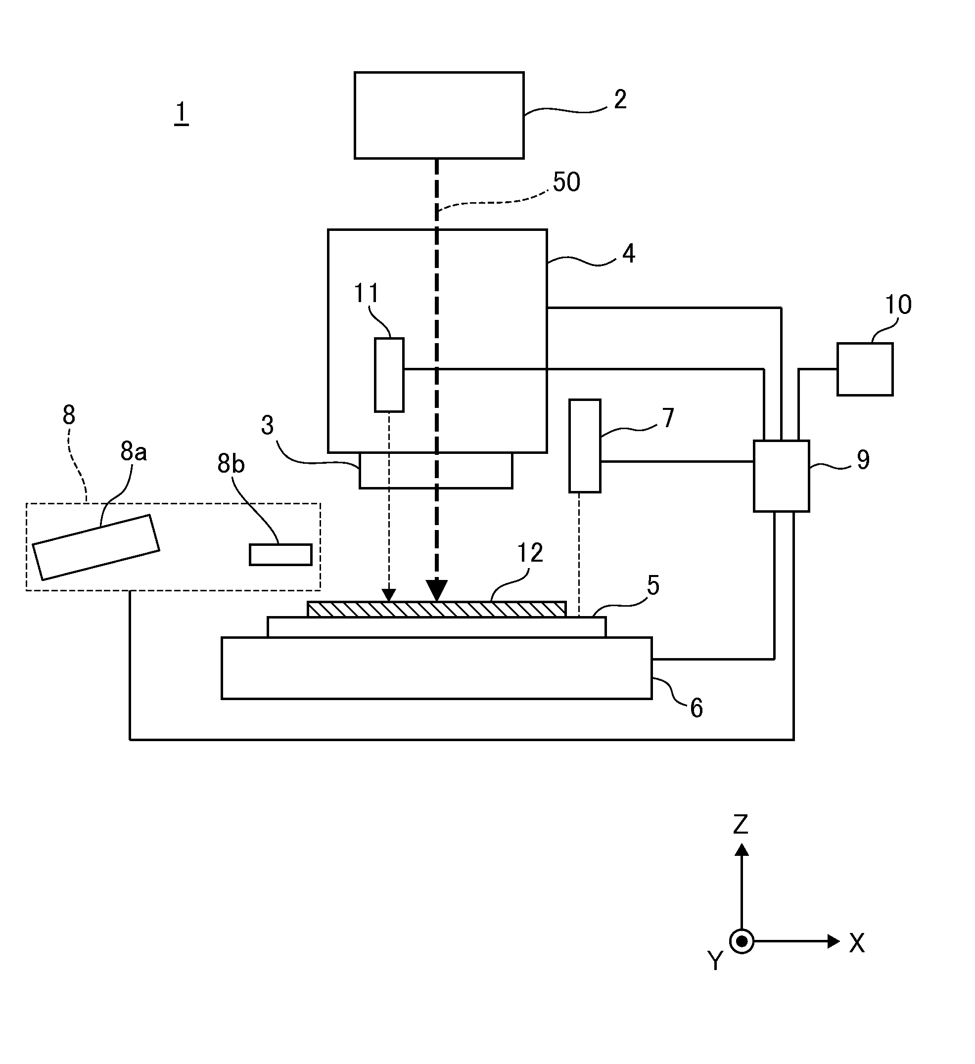
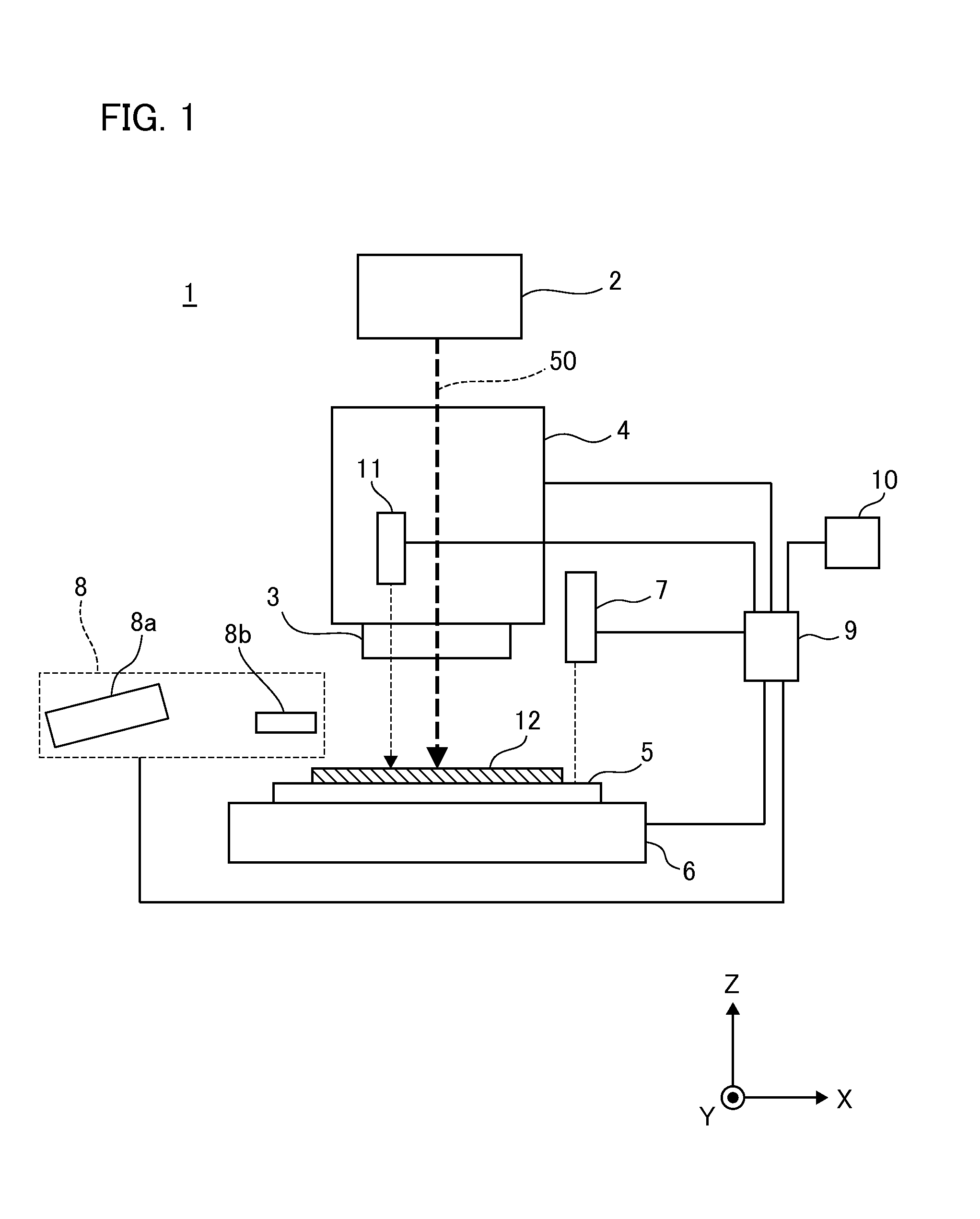
[0031]First, a description will be given of the configuration of an imprint apparatus according to an embodiment of the present invention. FIG. 1 is a schematic diagram illustrating the configuration of an imprint apparatus. The imprint apparatus according to the present embodiment is a processing apparatus that transfers the concave and convex pattern of a mold to a wafer (a substrate), i.e., a treatment object substrate, which is used for a semiconductor device manufacturing process, and is an apparatus that employs a photo-curing method among the imprint techniques. In the following drawings, a description will be given in which the Z axis is oriented in parallel to the irradiation axis of ultraviolet light for a mold, the X axis is oriented in the direction in which a mold measurement system moves with respect to an imprint head t...


PUM

PropertyMeasurementUnit
Threshold limitaaaaaaaaaa

Abstract

The imprint apparatus of the present invention molds an uncured resin on a substrate using a mold to form a resin pattern on the substrate. The apparatus includes a measuring device configured to project a light onto the mold, to receive a light scattered by the mold, and to measure the scattered light; and a controller. The controller is configured to store a reference signal, to cause the measuring device to measure the mold to obtain a measurement signal, and to obtain an index indicating a discrepancy between the measurement signal and the reference signal.

Description

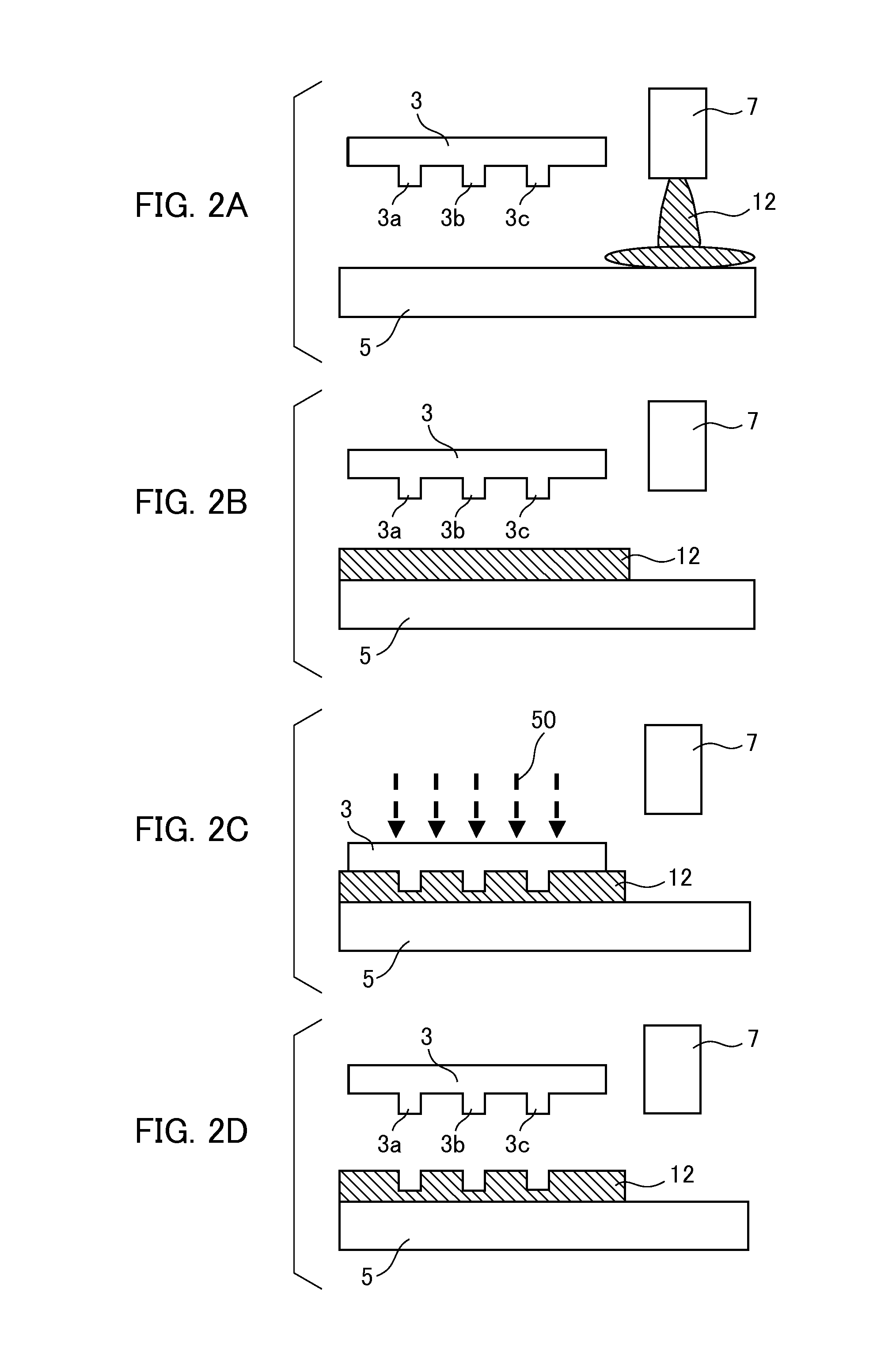
BACKGROUND OF THE INVENTION[0001]1. Field of the Invention[0002]The present invention relates to an imprint apparatus that molds an uncured resin on a substrate using a mold to form a resin pattern on the substrate, and an article manufacturing method using the same.[0003]2. Description of the Related Art[0004]As the demand for microfabrication of semiconductor devices increases, not only a conventional photolithography technique but also a microfabrication technique in which an uncured resin on a substrate is molded by a mold to thereby form a resin pattern on the substrate have attracted attention. This technique is also referred to as an “imprint technique”, by which a fine structure with dimensions of a few nanometers can be formed on the substrate. One example of imprint techniques includes a photo-curing method. An imprint apparatus employing the photo-curing method firstly applies an ultraviolet curable resin (imprint resin, photocurable resin) to the shot area (imprint area)...

Claims


Application Information

Patent Timeline
IPC IPC(8): B29C59/02
CPCB82Y10/00G03F7/0002B82Y40/00
Inventor MAEDA, HIRONORI
Owner CANON KK
Learn More