Heat dissipation apparatus for data center

a heat dissipation apparatus and data center technology, applied in lighting and heating apparatus, semiconductor/solid-state device details, instruments, etc., can solve the problems of large data center management cost by service providers, significant inconsistent temperature distribution of servers, energy waste in power consumption, etc., to reduce the maintenance expenditure of air conditioning and improve heat transfer in the data center

Inactive Publication Date: 2011-08-18
NOISE LIMIT APS
View PDF1 Cites 40 Cited by
  • Summary
  • Abstract
  • Description
  • Claims
  • Application Information

AI Technical Summary

Benefits of technology

[0009]Therefore, it is a primary objective of the invention to propose a heat dissipation apparatus for cooling one or more servers in a data center by means of combining the air channel with the flat tube or heat pipe for the purpose of cooling the heat source in the data center, and thereby greatly reducing the maintenance expenditure on the air conditioning.
[0010]It is a second objective of the invention to propose a heat dissipation apparatus for cooling one or more servers in a data center by means of further providing the cooling conduit together with the air channel so that a uniform temperature is distributed at each of the condenser portions for the purpose of greatly improving the heat transfer in the data center.
[0012]Therefore, it is a primary objective of the invention to propose a heat dissipation apparatus for cooling one or more servers in a data center by means of combining the cold plate with the flat tube or heat pipe so that cold water is supplied in the first water pipe to flow into the cold plate for cooling the heat at the condenser portion, and the second water pipe guides hot water to flow out of the cold plate because the cold water becomes hot water after heat absorption within the cold plate of the condenser portion, and thereby allowing the hot water to be cooled into cold water again to achieve the green and recyclable solution friendly to the environment.

Problems solved by technology

However, such conventional cooling approach may cause energy waste in power consumption and produce a large cost for managing the data center by the service providers.
However, such conventional cooling approach may also cause the significantly inconsistent temperature distribution in each server in the data center.
Moreover, the heat generated by some servers cannot be removed effectively because the servers are located further away from the huge air conditioning device, and thus the servers will be damaged from the uncontrollable heat.

Method used


Image

  • Heat dissipation apparatus for data center
  • Heat dissipation apparatus for data center
  • Heat dissipation apparatus for data center

Examples


Embodiment Construction

[0021]A heat dissipation apparatus for cooling a plurality of servers in a data center has been disclosed in the invention; wherein the principles of heat transfer employed in a heat pipe or flat tube may be easily comprehended by those of ordinary skill in relevant technical fields, and thus will not be further described hereafter. Meanwhile, it should be noted that the drawings referred to the following paragraphs only serve the purpose of illustrating structures related to the characteristics of the disclosure, and are not necessarily drawn according to actual scales and sizes of the disclosed objects.

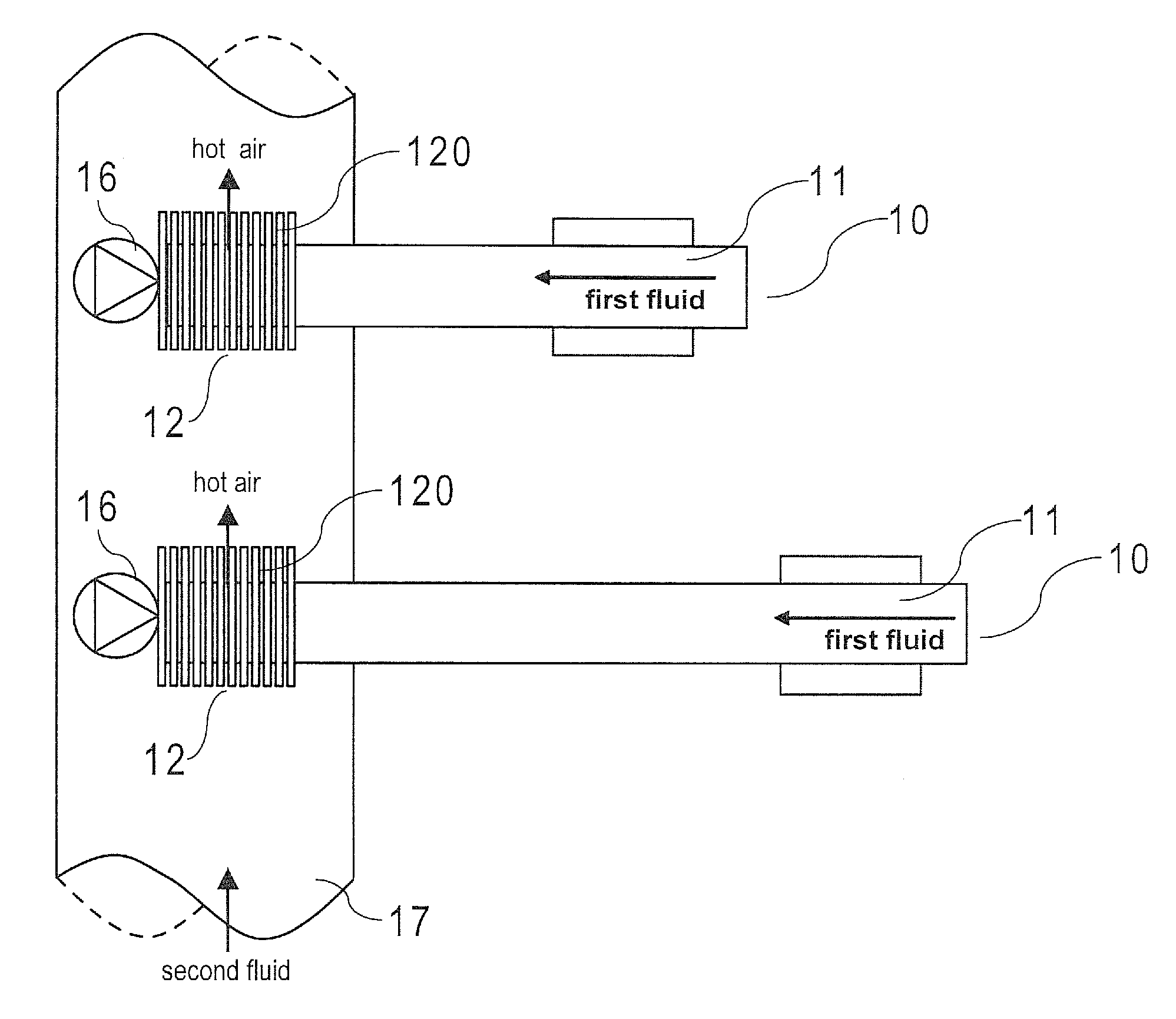
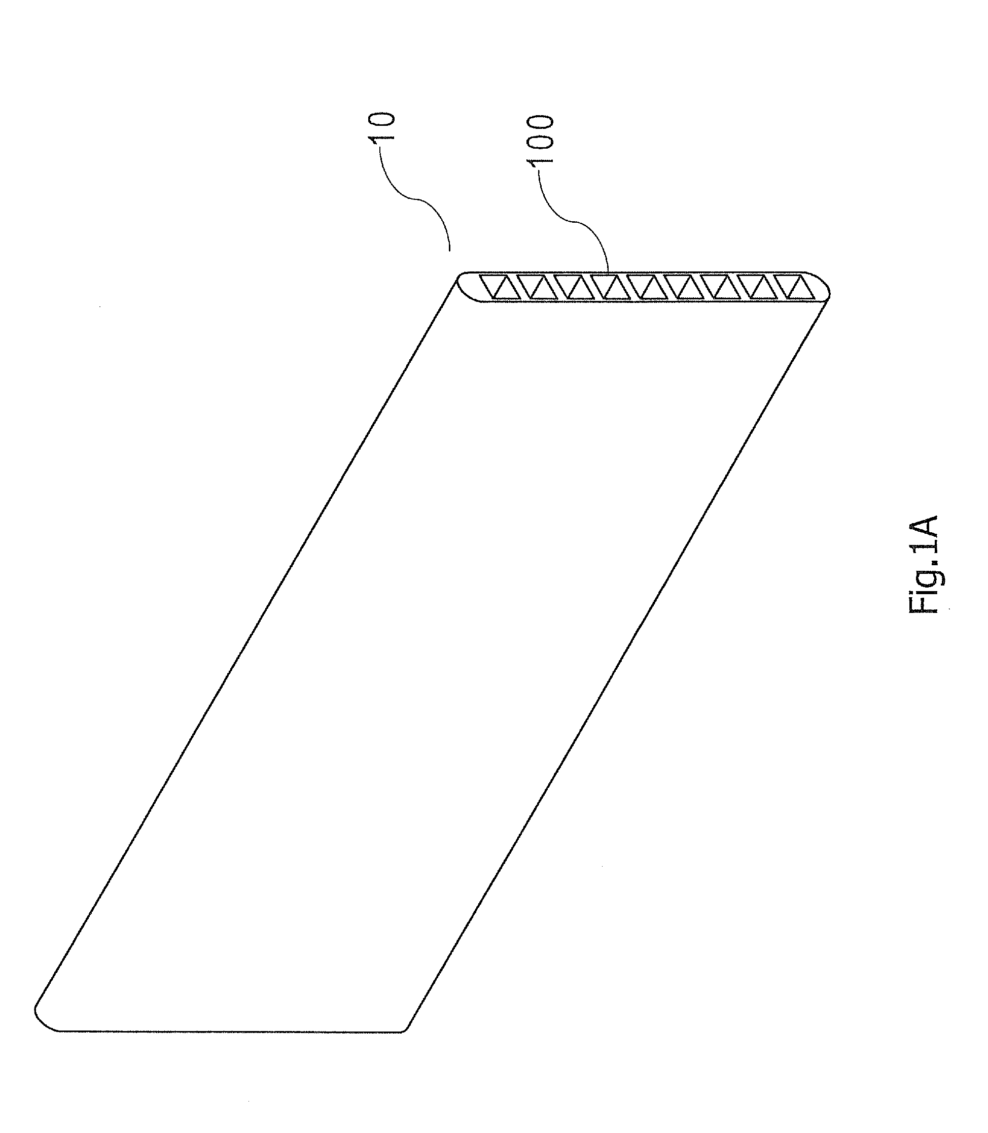
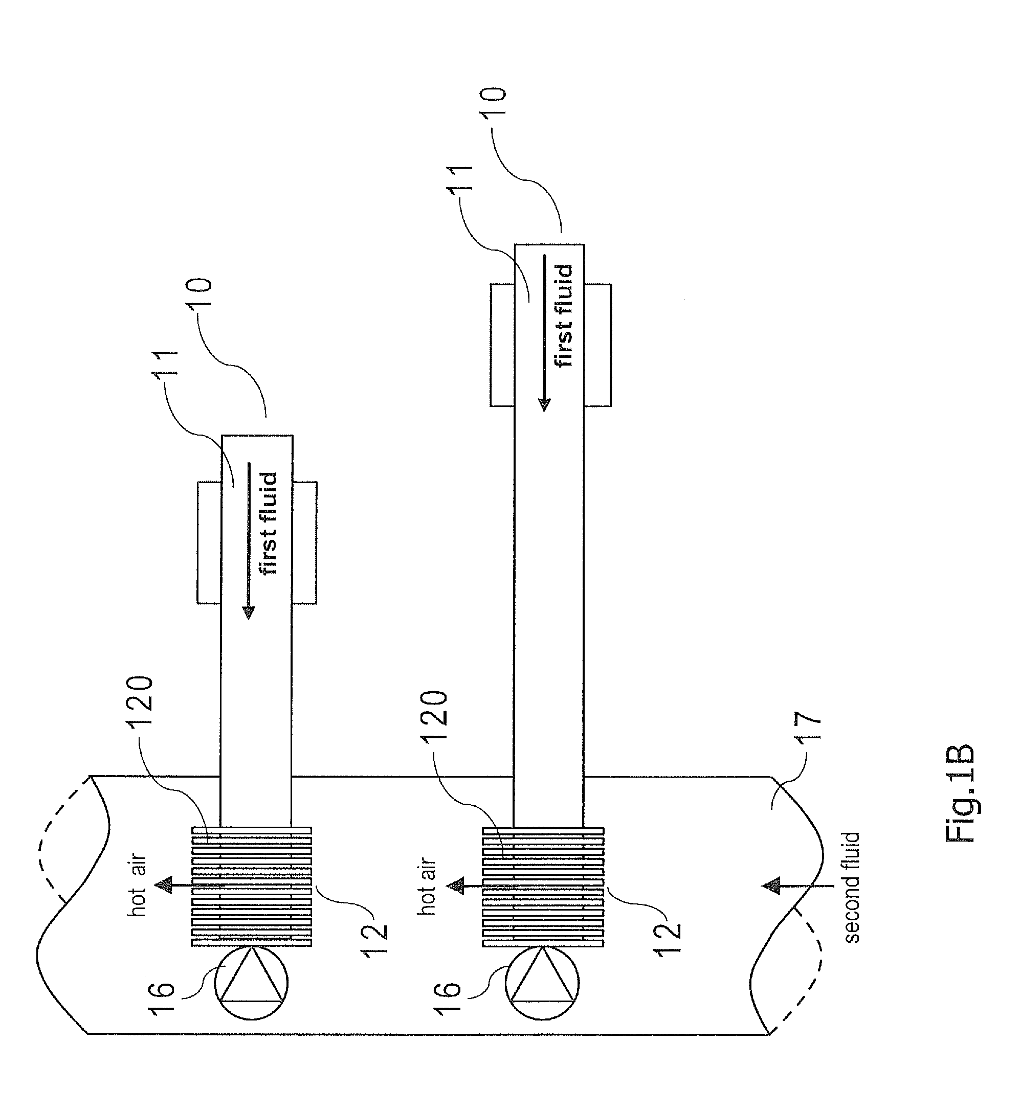
[0022]A heat dissipation apparatus for cooling a plurality of servers (not shown) in a data center according to a first preferred embodiment of the invention is disclosed herein. The heat dissipation apparatus comprises two heat transfer means and an air channel. Each heat transfer means is a flat tube in the first preferred embodiment of the invention. Refer to FIG. 1A, it is a 3D ...


PUM


Abstract

The present invention discloses a heat dissipation apparatus that comprises a heat transfer means and an air channel. The heat transfer means is filled with a first fluid, and it has an evaporation portion and a condenser portion where the evaporation portion receives heat from at least one server and the heat is transmitted to the condenser portion through the first fluid. The air channel receives a second fluid to transfer the heat from the condenser portion into a predetermined space. The first fluid is different than the second fluid.

Description

CROSS-REFERENCE TO RELATED APPLICATIONS[0001]This application is a Continuation in-part of, and claims a priority to the U.S. application Ser. No. 12 / 704,963 entitled “HEAT DISSIPATION APPARATUS FOR DATA CENTER” filed on Feb. 12, 2010. Also, the disclosure of the U.S. application Ser. No. 12 / 704,963 is incorporated herein.BACKGROUND OF THE INVENTION[0002]1. Technical Field[0003]The invention relates to a heat dissipation apparatus for cooling at least a server in a data center, and more particularly to the heat dissipation apparatus for cooling servers in a data center using one of the heat pipes, heatsinks, heat pipe assisted heat sinks and vapor chambers or combination thereof to effectively remove heat source from one or more servers in the date center.[0004]2. Description of Related Art[0005]The conventional cooling approach to removing multiple heat sources from a plurality of servers in a data center is to apply a plurality of air conditioning devices arranged in a place adjac...

Claims


Application Information

Patent Timeline
Patent Type & Authority Applications(United States)
IPC IPC(8): F28D15/04
CPCF28D15/0233F28D15/0266F28F1/24G06F1/20G06F2200/201H01L23/427H01L2924/0002H01L23/467H01L23/473H05K7/20809H01L2924/00
Inventor LANGE, TORBEN B.CHEN, CHI-LIANGHORSTMEYER, ROBERTPERSON, JR., GREER P.SENIOR, ROBERT
Owner NOISE LIMIT APS
Why Eureka
Try Eureka