
Thin-film photochemical vapour generation

a thin film, photochemical technology, applied in the direction of evaporation, separation process, instruments, etc., can solve the problems of reducing the efficiency of vapour generation, wasting samples, and limiting the use of semi-metals and mercury, so as to reduce the effect of extraneous absorption, enhance irradiation times, and high efficiency

Inactive Publication Date: 2011-08-11
NAT RES COUNCIL OF CANADA
View PDF11 Cites 5 Cited by
  • Summary
  • Abstract
  • Description
  • Claims
  • Application Information

AI Technical Summary

Benefits of technology

[0024]The present simple, yet efficient thin-film vapour generator and process are surprisingly effective for use with photochemical vapour generation for detection and / or quantification of an expanded suite of analytes, while being applicable to conventional cold vapour and hydridization reactions as well. Use of a thin-film exposed to a UV field is thought to mitigate the effects of extraneous absorption of source intensity as it penetrates the liquid medium, thereby delivering UV intensity with high efficiency, minimizing the need for enhanced irradiation times for the processing of coloured (absorbing) samples (Vieira 2007). Amalgamation of photochemical reactions with thin film generation and gas-liquid phase separation has now achieved the benefits of all of these principles in a single unit, providing a simple and effective way of enhancing generation of an expanded suite of elements.
[0025]Apart from the typical advantages which accrue with use of a conventional VG reactor, the thin-film photochemical vapour generator (TF-PVG) offers several unique additional features: (i) rapid and very efficient separation of the reaction products is achieved due to the large surface-to-volume ratio provided by the thin liquid film; (ii) production of sample aerosol is minimized permitting a cleaner sample matrix to be admitted to the detector; (iii) interferences from concomitant elements and potential decomposition of the products by UV is significantly reduced because of the extremely rapid phase separation and analyte transport; (iv) flexible UV irradiation time can be achieved, providing a more universal application; (v) reaction efficiency is optimized as the UV efficiently penetrates the thin liquid film; and (vi) nanomaterials (e.g. TiO2) can be conveniently coated onto the sample support element to provide a significant enhancement in PVG efficiency for certain elements, e.g. Se(VI) and Te(VI).

Problems solved by technology

This is wasteful of sample and has an efficiency of typically about 2%.
However, conventional hydride and cold vapour generation, the most popular vapour generation techniques, are limited to semi-metals and mercury, respectively.

Method used


Image

  • Thin-film photochemical vapour generation
  • Thin-film photochemical vapour generation
  • Thin-film photochemical vapour generation

Examples


example 1

Thin-Film Photochemical Vapour Generator

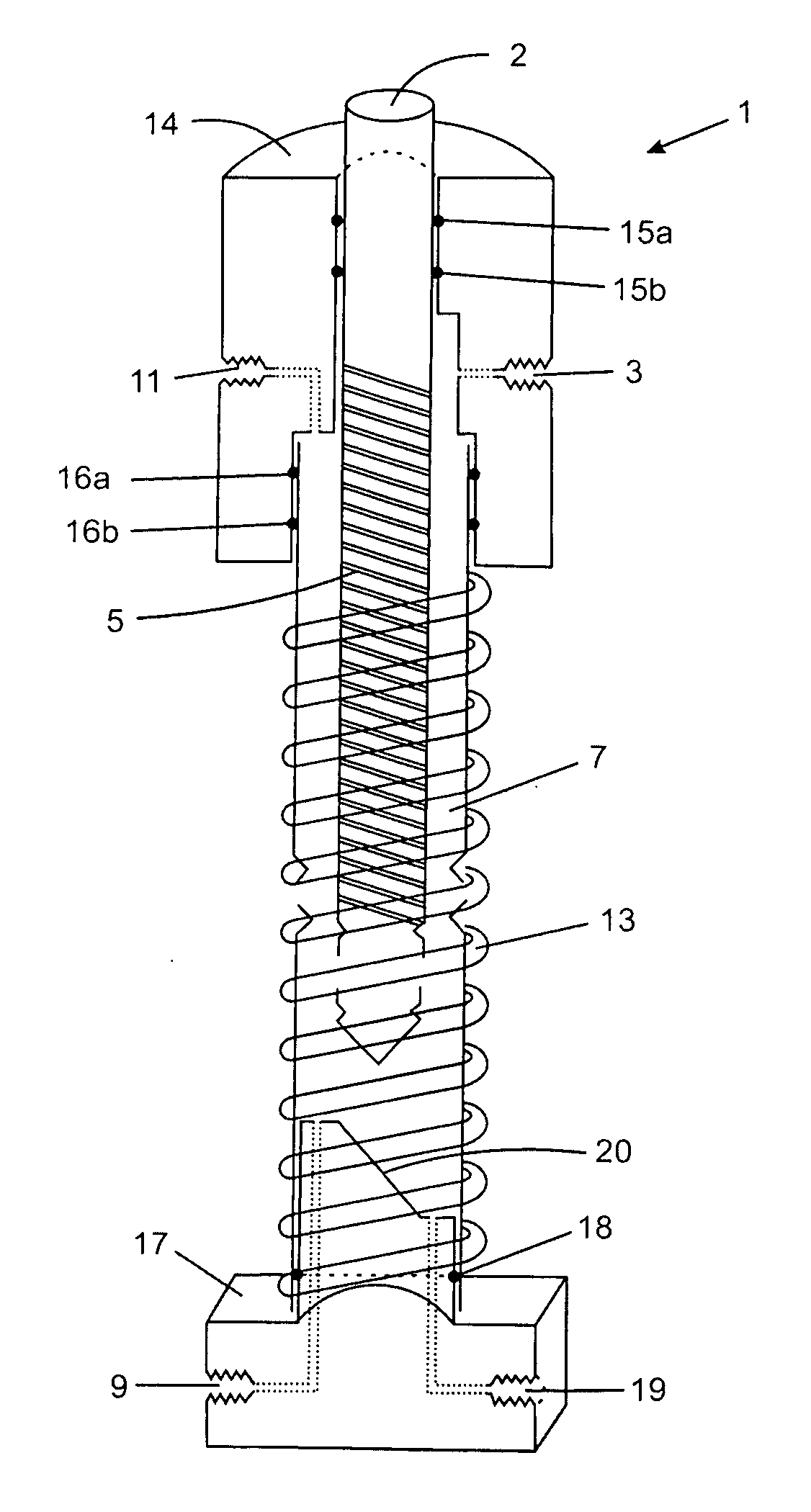
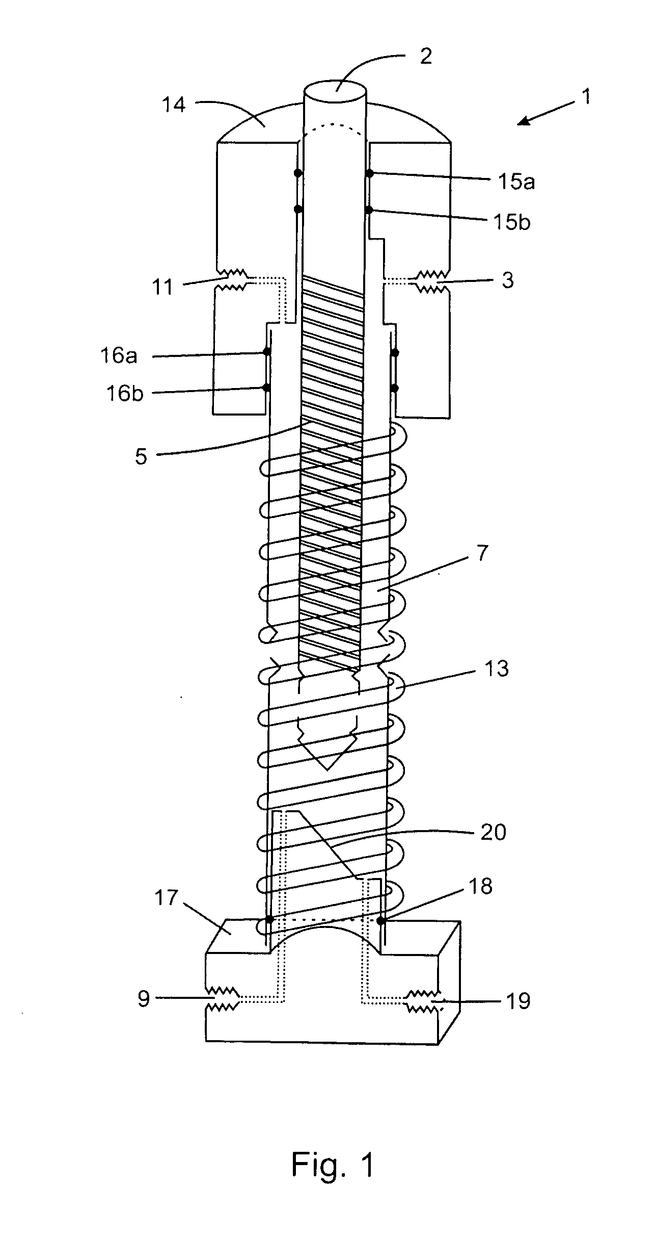
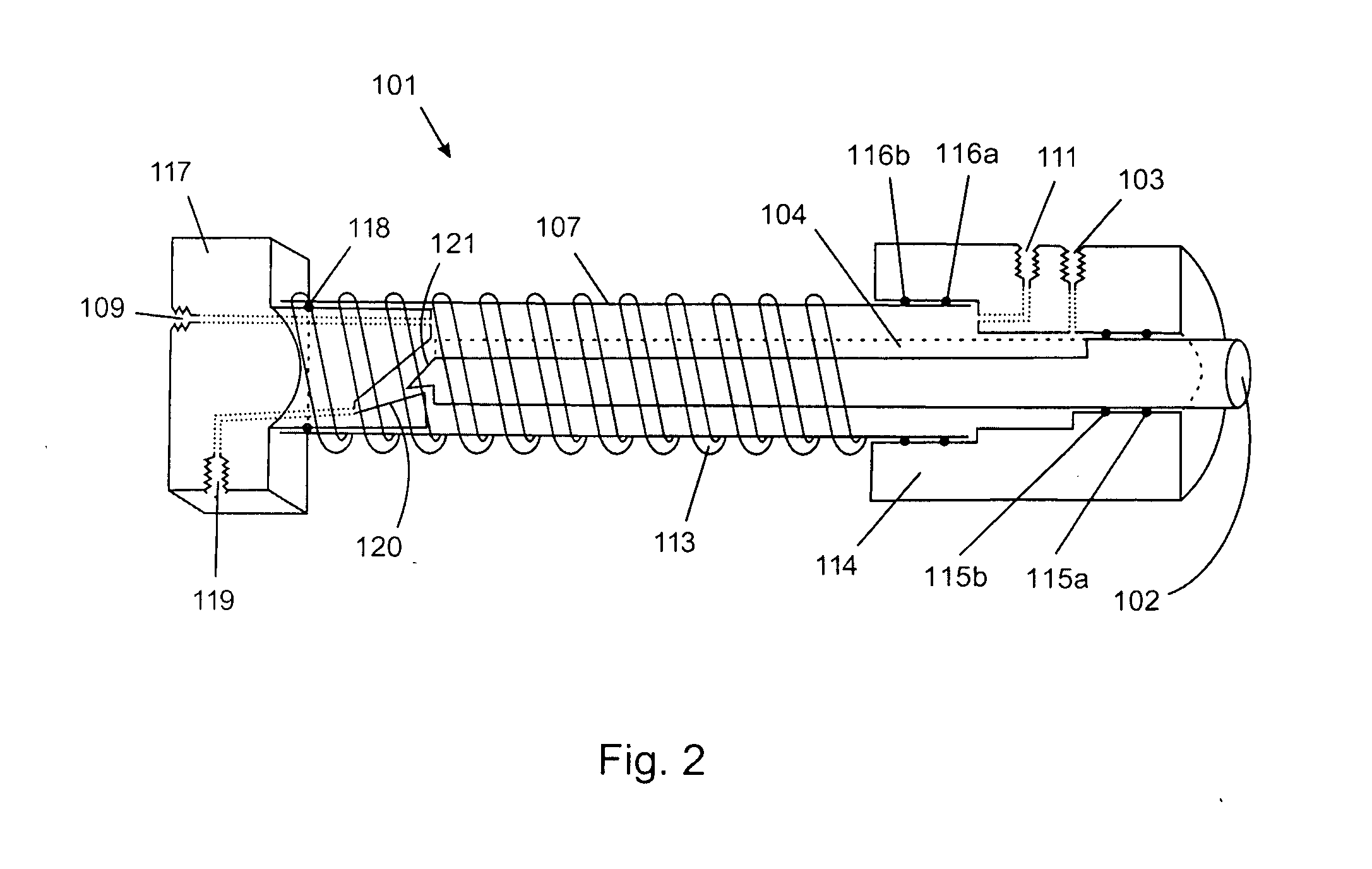
[0041]FIG. 1 provides a schematic drawing of a first embodiment of a thin-film photochemical vapour generator of the present invention in vertical orientation. With reference to FIG. 1, the thin-film photochemical vapour generator 1 integrates both vapour generation and gas-liquid separation functions utilizing a 6 mm o.d. vertical central quartz rod 2 onto which a liquid sample containing a precursor compound of an analyte is pumped through sample inlet 3 to yield a thin liquid film on the surface of the rod. The surface of the rod is fashioned into a screw design 5 to increase surface area of the rod in order to perturb what would otherwise be an unencumbered flow of liquid down a smooth surface under the influence of gravity, thereby enhancing sample residence time in the generator. The thin liquid flow facilitates rapid escape of any generated volatile species from the condensed phase. The rod is housed within a concentric 13 mm o.d. quart...

example 2

Sample Analysis Using TF-PVG

Procedure

[0047]Once the Ar plasma and the UV lamp of the TF-PVG of Example 1 are stabilized, the PVG generator is brought on-line and volatile species are generated when analyte standard solutions containing formic or acetic acid at varying concentrations are delivered to the TF-PVG. Gaseous products, simultaneously separated from the liquid phase within the generator, are flushed by the Ar carrier gas to the ICP torch for optical emission measurements. All experimental conditions are optimized for maximum response for each analyte. A blank is measured before each run using solutions containing only sub-boiling distilled LMW acids (ammonia and the LMW organic acid in the case of iron). No blank signal is generally detected; however, it is noteworthy that analytical grade formic acid produces a very high blank for iron and nickel before purification.

[0048]Test samples of nominal 0.25 g of CRMs DORM-3 and DOLT-4 are weighed into Teflon™ digestion vessels (C...


PUM

PropertyMeasurementUnit
internal volumeaaaaaaaaaa
lengthaaaaaaaaaa
lengthaaaaaaaaaa

Abstract

A photochemical vapour generator is disclosed having a reaction chamber with a liquid sample inlet, a carrier gas inlet and a carrier gas outlet. A liquid sample support surface for supporting a film of a liquid sample is in the reaction chamber. A source of ultraviolet radiation is positioned in radiative contact with the liquid sample support surface. Also described is a process for detecting and / or quantifying an analyte by providing a liquid film of a sample containing an organic acid or a salt thereof and a precursor compound of the analyte, exposing the liquid film to ultraviolet radiation to generate a volatile species of the analyte, separating the volatile species from the liquid film to form a vapour containing the volatile species, and directing the vapour to a detector to detect and / or quantify the analyte in the vapour. Amalgamation of photochemical reactions with thin film generation and gas-liquid phase separation achieves the benefits of all of these principles in a single unit, providing a simple and effective way of enhancing generation of an expanded suite of elements.

Description

CROSS-REFERENCE TO RELATED APPLICATIONS[0001]This application claims the benefit of U.S. Provisional Patent Application Ser. No. 61 / 336,529 filed Jan. 21, 2010, the entire contents of which is herein incorporated by reference.FIELD OF THE INVENTION[0002]The present invention is related to detection and / or quantification of an analyte in a sample. In particular, the present invention relates to photochemical apparatuses and processes for generating volatile species of an analyte from a sample containing non-volatile precursors of the analyte.BACKGROUND OF THE INVENTION[0003]Sample introduction for detection / quantification of trace elements by atomic spectrometry has relied greatly on the use of solution nebulization techniques. This is wasteful of sample and has an efficiency of typically about 2%. In addition, the entire sample is admitted to the detector volume (whether it is a graphite furnace for AAS or an Ar carrier gas for ICP-OES or ICP-MS) carrying with it the matrix constitu...

Claims


Application Information

Patent Timeline
Patent Type & Authority Applications(United States)
IPC IPC(8): G01N33/00B01J19/08
CPCB01D1/065Y10T436/25875B01D3/346
Inventor STURGEON, RALPHZHENG, CHENGBIN
Owner NAT RES COUNCIL OF CANADA
Learn More