Eureka AIR delivers breakthrough ideas for toughest innovation challenges, trusted by R&D personnel around the world.

Remote Detection and Measurement of Objects

Active Publication Date: 2011-07-28
RADIO PHYSICS SOLUTIONS
View PDF22 Cites 34 Cited by
  • Summary
  • Abstract
  • Description
  • Claims
  • Application Information

AI Technical Summary

Benefits of technology

[0047]An advantage of the invention is that effective detection of threat objects at stand-off distances may be accomplished.
[0048]A further advantage of the invention is that detection of threat objects using a portable device may be achieved.
[0049]A further advantage is that the detection of smaller dimensions (e.g. gun barrel dimensions and / or caliber) is enabled.BRIEF DESCRIPTION OF THE FIGURES
[0050]Embodiments of the invention will now be described in detail, by way of example, with reference to the accompanying drawings, in which:
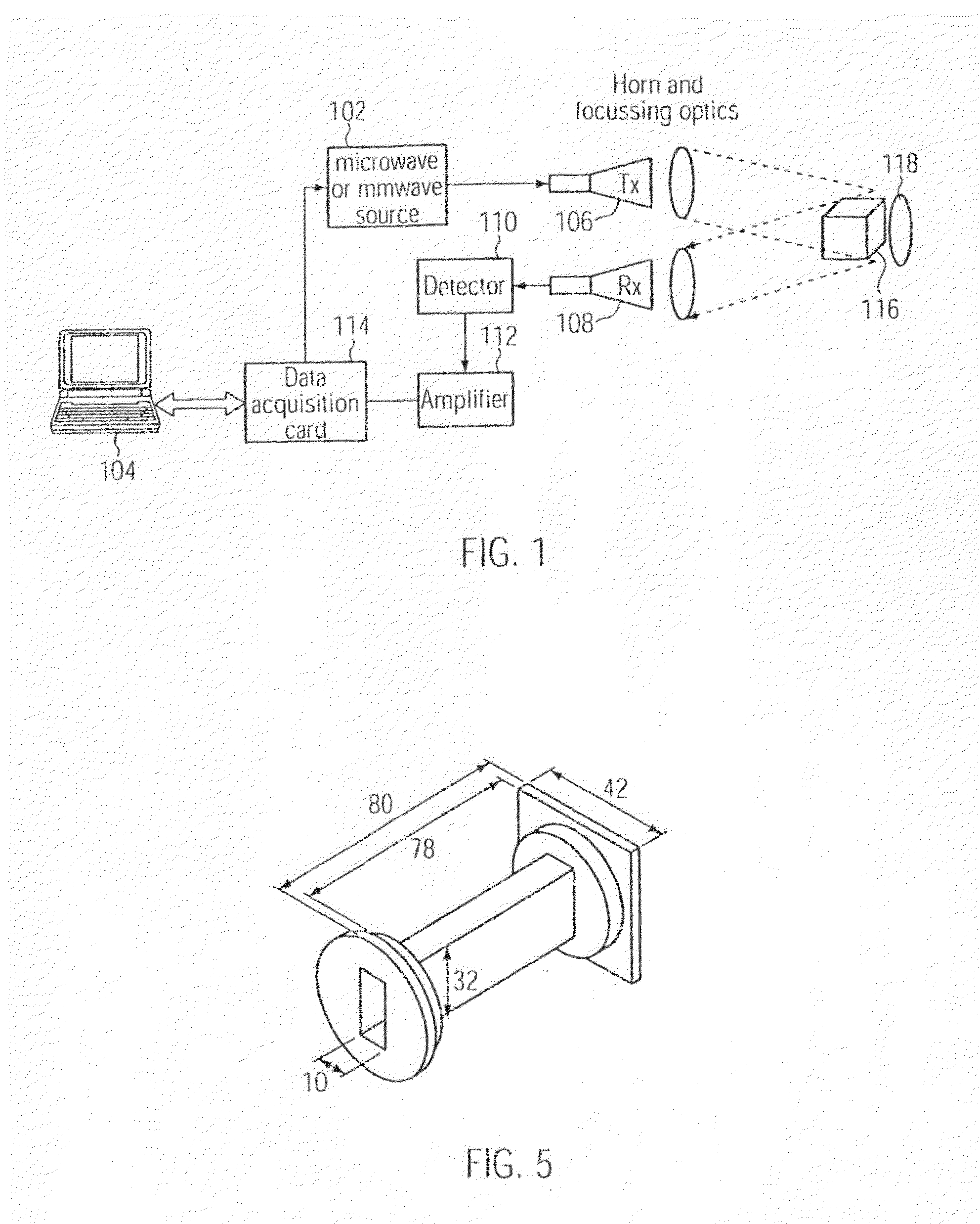
[0051]FIG. 1 is a block diagram of an object detection system according to some embodiments of the invention;
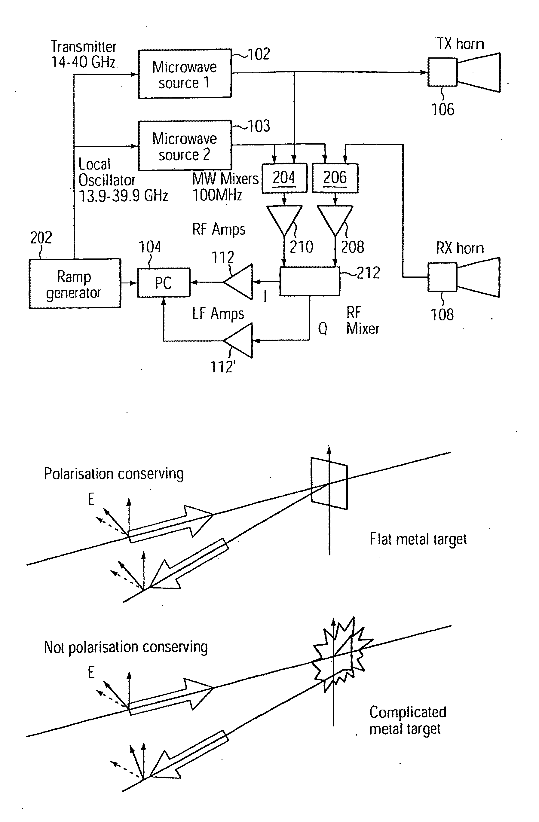
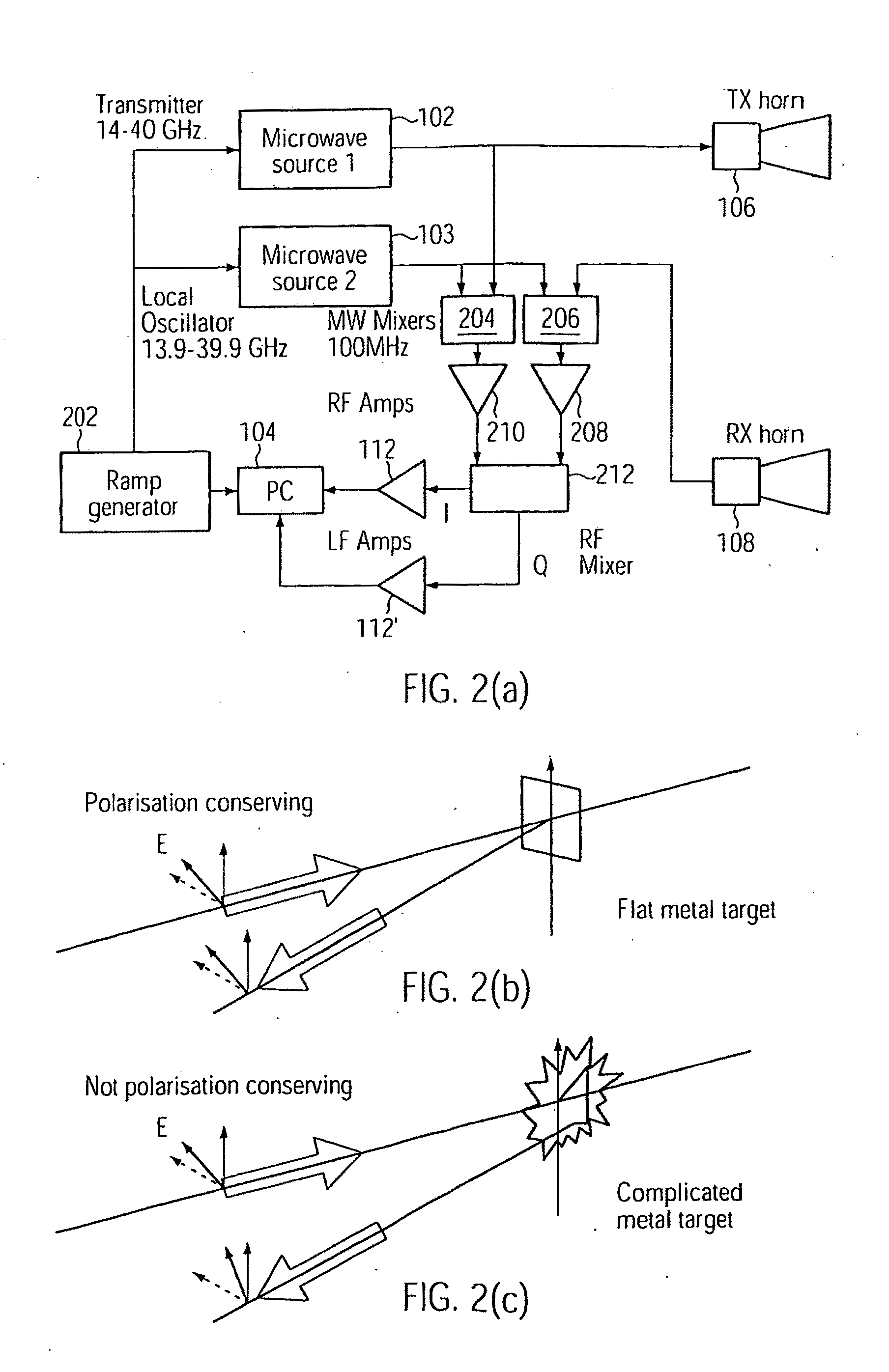
[0052]FIG. 2(a) shows a block diagram of an object detection system according to some embodiments of the invention, and FIGS. 2(b) and 2(c) show the different behaviour of smooth and jagged conducting targets in response to linearly polarized microwave radiation;

Problems solved by technology

However, the conventional detectors used at airports may be unable to determine the dimensions of objects to any significant degree, and thus may be unable to distinguish between objects of different types, i.e. harmless (belt buckles, cameras), and potentially dangerous (guns, knives).
The detection of concealed weapons, especially handguns, may be a very great problem for security applications that currently cannot be policed without a non-portable system, for example random checks in an urban environment.
However, such techniques have not been heretofore used for detecting and measuring metal objects.
In the aforementioned patent documents, the low frequency of operation makes the angular resolution of the antennae poor and the wide field of view makes it difficult to single out particular targets and / or to determine on which part of the target the threat is situated.
Passive systems, though giving more realistic images, tend to be slow and show poor contrast for dielectric targets.
Active illumination systems can be acquired faster, but may suffer from strong reflections from benign objects such as the human body, which make it difficult to distinguish from metal threat objects.
This makes their deployment in many applications difficult.
It is apparent that systems which can identify threat objects at stand-off distances may have many applications, where conventional metal detector booths are inappropriate.

Method used


Image

  • Remote Detection and Measurement of Objects
  • Remote Detection and Measurement of Objects
  • Remote Detection and Measurement of Objects

Examples


Embodiment Construction

[0073]Embodiments of the present invention now will be described more fully hereinafter with reference to the accompanying drawings, in which embodiments of the invention are shown. This invention may, however, be embodied in many different forms and should not be construed as limited to the embodiments set forth herein. Rather, these embodiments are provided so that this disclosure will be thorough and complete, and will fully convey the scope of the invention to those skilled in the art. Like numbers refer to like elements throughout.

[0074]It will be understood that, although the terms first, second, etc. may be used herein to describe various elements, these elements should not be limited by these terms. These terms are only used to distinguish one element from another. For example, a first element could be termed a second element, and, similarly, a second element could be termed a first element, without departing from the scope of the present invention. As used herein, the term ...


PUM


Abstract

Provided are methods of using electromagnetic waves for detecting metal and / or dielectric objects. Methods include directing microwave and / or mm wave radiation in a predetermined direction using a transmission apparatus, including a transmission element; receiving radiation from an entity resulting from the transmitted radiation using a detection apparatus; and generating one or more detection signals in the frequency domain using the detection apparatus. Methods may include operating a controller, wherein operating the controller includes causing the transmitted radiation to be swept over a predetermined range of frequencies, performing a transform operation on the detection signal(s) to generate one or more transformed signals in the time domain, and determining, from one or more features of the transformed signal, one or more dimensions of a metallic or dielectric object upon which the transmitted radiation is incident. A system and method for remote detection and / or identification of a metallic threat object using late time response (LTR) signals is also disclosed.

Description

TECHNICAL FIELD[0001]The present invention relates to the detection of objects, and more particularly, to techniques for remote detection and measurement of objects.BACKGROUND ART[0002]It is well known to use electromagnetic radiation to detect the presence of objects (e.g. handheld detectors used for detecting objects on or under the ground, and walk-through arches at airports).[0003]However, the conventional detectors used at airports may be unable to determine the dimensions of objects to any significant degree, and thus may be unable to distinguish between objects of different types, i.e. harmless (belt buckles, cameras), and potentially dangerous (guns, knives).[0004]The detection of concealed weapons, especially handguns, may be a very great problem for security applications that currently cannot be policed without a non-portable system, for example random checks in an urban environment. The use of microwaves (electromagnetic waves with wavelengths in the centimeter to millime...

Claims


Application Information

Patent Timeline
IPC IPC(8): G01R27/04G06N3/02G06F15/00
CPCG01S7/411G01S13/887G01S13/04G01S7/417G01N22/00G01S13/89G01V8/005G01S7/024G01S13/08
Inventor BOWRING, NICHOLASANDREWS, DAVIDDDINE REXGUI, NACERHARMER, STUART
Owner RADIO PHYSICS SOLUTIONS
Why Eureka
Eureka Blog
Learn More