Image reading apparatus, multifunction printer, and image reading method
a multi-function printer and image reading technology, applied in the direction of digital output to print units, instruments, television systems, etc., can solve the problems of increasing unwanted radiation (emi: electromagnetic interference) of scanners, generating image noise, and difficult to suppress unwanted radiation, so as to maintain image quality. the effect of quality
- Summary
- Abstract
- Description
- Claims
- Application Information
AI Technical Summary
Benefits of technology
Problems solved by technology
Method used
Image
Examples
first embodiment
[First Embodiment]
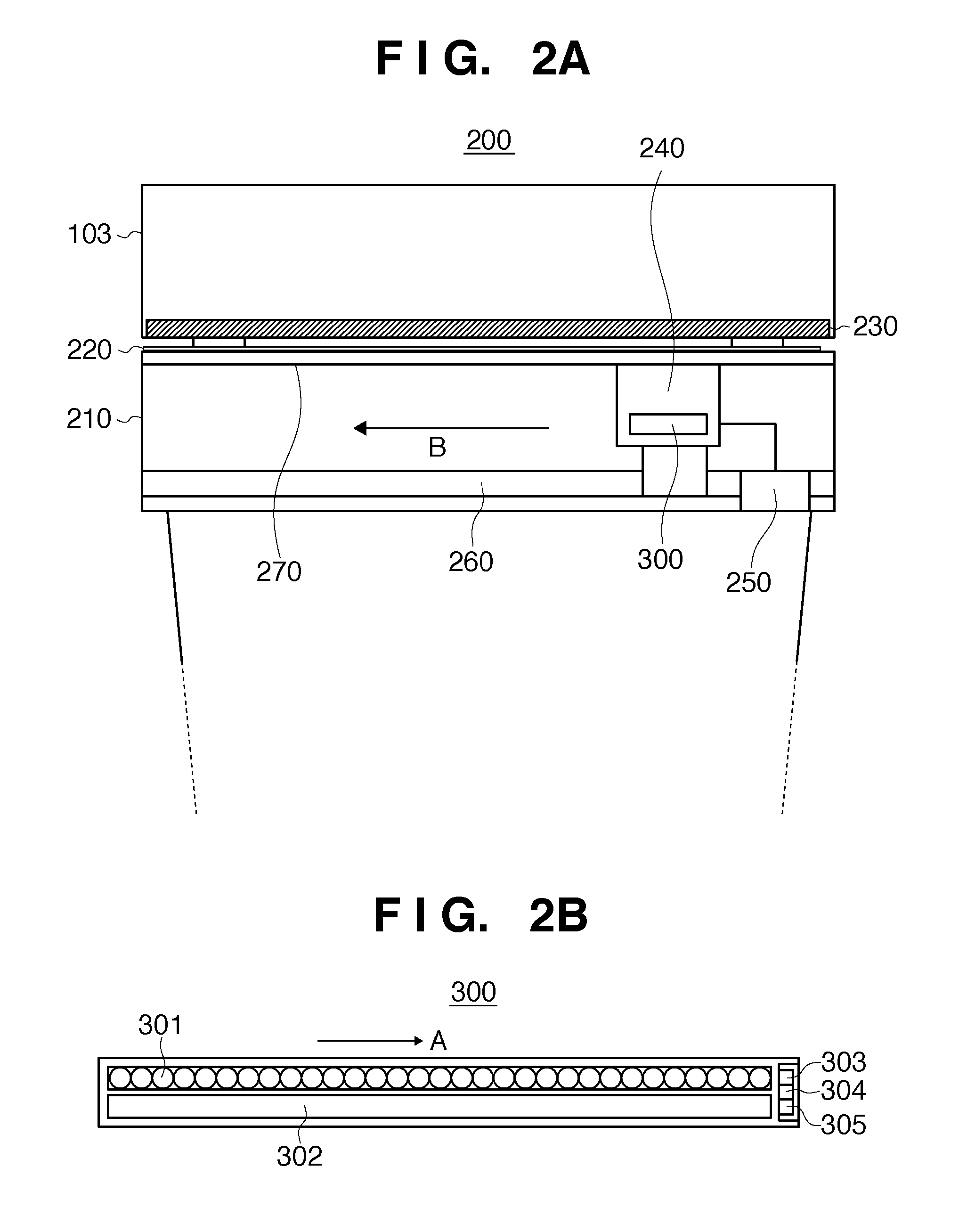
[0048]FIG. 6 is a block diagram showing the sequence of image reading processing executed in a CIS unit. FIG. 6 shows image reading processing 16 for the nth line, and image reading processing 17 for the (n+1)th line. In a CIS unit 300, after the nth line signal is supplied (16a), a data signal received on a previously read line ((n−1)th line) is latched (16b). Simultaneously when the latched data signal is transferred, a photodiode (photoelectric transducer) 300a receives an image data signal to be processed on the next line ((n+1)th line) (16c). The same processes are performed even for the next line ((n+1)th line) (17a, 17b, and 17c).
[0049]FIG. 7 is a timing chart of the image reading processing shown in FIG. 6. After a line signal (SP) 18a is supplied, a timing generator circuit 11d supplies a data latch signal (PCM) 18c in synchronism with a driving signal (CLK) 18b after a specific period of time (upon the lapse of a specific number of clocks). After the line...
second embodiment
[Second Embodiment]
[0068]FIG. 11 is a timing chart of image reading processing according to the second embodiment. In FIG. 11, the same reference numerals and symbols as those in the timing chart of image reading processing shown in FIG. 7 according to the first embodiment denote the same signals and periods, and a description thereof will not be repeated.
[0069]In the second embodiment, the frequency of the driving signal is set to be different between the data latch period and the light reception / data transfer / dummy period in the one-line cycle of image reading.
[0070]As is apparent from a comparison between FIGS. 11 and 7, in the second embodiment, the frequency of the driving signal is set to different values between a data latch period 18f and a light reception / data transfer / dummy period 18g. In the second embodiment, no SSCG spread modulation is performed in the data latch period 18f. Thus, since no high-frequency driving signal is spread, the EMI radiation level rises, compared...
PUM
 Abstract
Description
Claims
Application Information
 - R&D
- Intellectual Property
- Life Sciences
- Materials
- Tech Scout
- Unparalleled Data Quality
- Higher Quality Content
- 60% Fewer Hallucinations
Browse by: Latest US Patents, China's latest patents, Technical Efficacy Thesaurus, Application Domain, Technology Topic, Popular Technical Reports.
© 2025 PatSnap. All rights reserved.Legal|Privacy policy|Modern Slavery Act Transparency Statement|Sitemap|About US| Contact US: help@patsnap.com


