Method and system for video based image detection/identification analysis for fluid and visualization control

a technology of identification analysis and video based image, applied in the field of video based image detection/identification analysis for fluid and visualization control, can solve the problems of compromising surgery, difficult tasks, and additional time for surgery, and achieve the effects of improving image quality, improving image quality, and improving video imag

Active Publication Date: 2011-09-29
STRYKER CORP
View PDF25 Cites 21 Cited by
  • Summary
  • Abstract
  • Description
  • Claims
  • Application Information

AI Technical Summary

Benefits of technology

The present invention provides an improved video image for a surgical site by automatically selecting the optimal functions to be controlled in order to maximize the quality of the video image provided on a display for a surgeon during a medical procedure. The invention detects and identifies specific conditions that degrade the quality of the video image, such as bubbles, debris, bleeders, and smoke, and controls various devices to improve the image quality. The invention operates as a closed system by receiving direct video information as to the quality of an image and then controlling devices to maintain image quality.

Problems solved by technology

This manual task can be difficult and lead to additional time for conducting a surgery and potentially compromise the surgery if the images are not acceptable.
The system described above, however, is limited to an operating control device 17 for a pump that only controls liquid inflow for the arthroscope 14 and liquid outflow from a separate shaver 15.
Further, the prior art system is limited to processing red, blue and green video signal components.
Finally, the FIG. 1 system is limited to controlling flow pressure / inflow and outflow rates in order to obtain a desired video image.

Method used


Image

  • Method and system for video based image detection/identification analysis for fluid and visualization control
  • Method and system for video based image detection/identification analysis for fluid and visualization control
  • Method and system for video based image detection/identification analysis for fluid and visualization control

Examples


Embodiment Construction

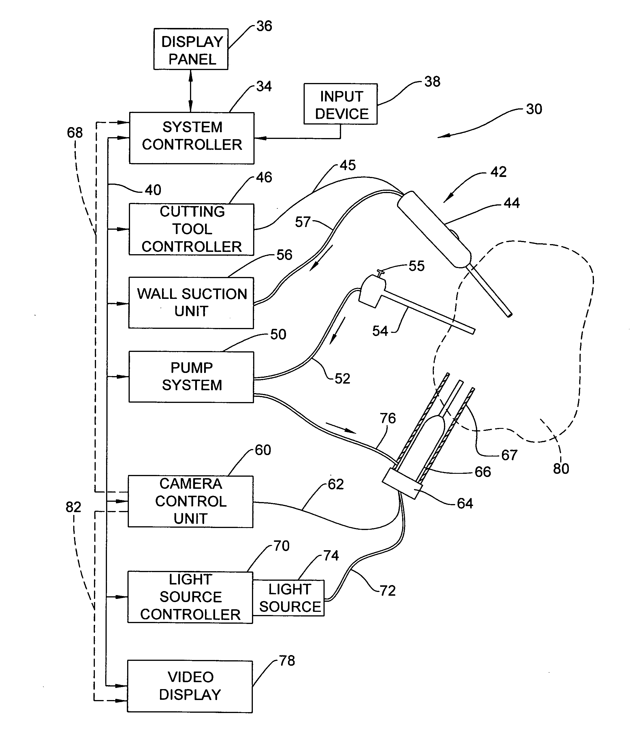
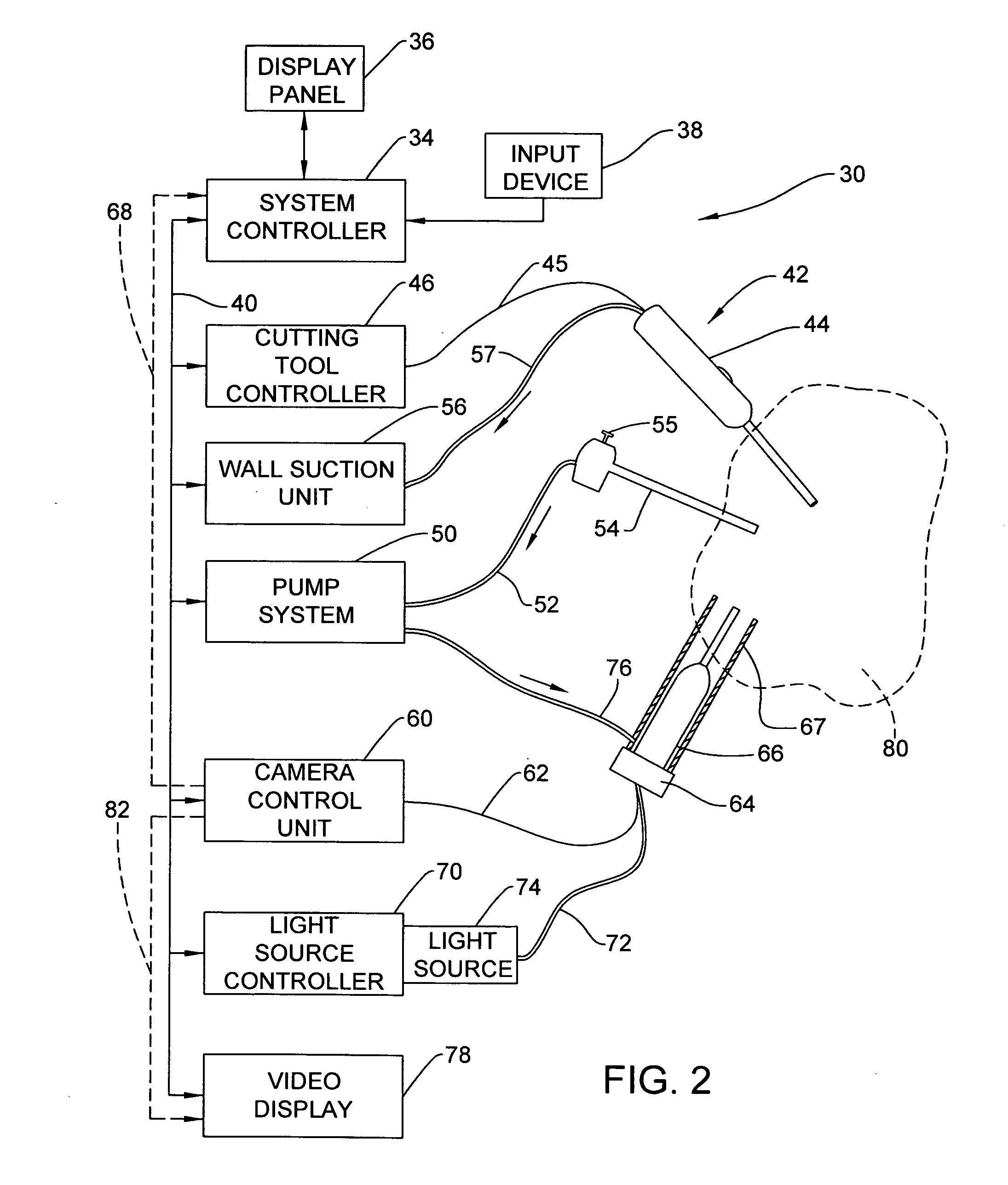
[0030]FIG. 2 illustrates an integrated surgical control system 30 that includes a system controller 34 having a display panel 36 and an input device 38. The system controller 34 is connected by a computer network 40 to communicate with a plurality of surgical devices. The devices may include a cutting tool 42, such as a surgical shaver, having a handpiece 44 connected by a signal line 45 to a cutting tool controller 46 that communicates with the system controller 34 over the network 40. The surgical control system 30 can be an arthroscopic surgical control system.

[0031]The surgical control system 30 includes a pump system 50 connected to suction tubing 52 for providing suction to a cannula 54 having a stop cock 55. In some embodiments, the pump system 50 includes a peristaltic pump. While the cannula 54 is only shown as providing a suction flow path, in some embodiments, the cannula 54 can be used to define a portal into the surgical site into which other types of tools or devices c...


PUM


Abstract

In a surgical system, a system controller executes a video signature identification and image control routine to maintain quality of a video image taken by a video camera located at a surgical site and provided on a video display. The system includes a video camera / light source handpiece for insertion into a patient body. A tool is inserted separately into the surgical site. Fluid input into the surgical site is provided by a liquid pump or by an insufflator. Video signals are analyzed and fluid input / output, fluid pressure, and / or tool operation is automatically controlled to maintain image quality of the surgical site without manual adjustments.

Description

CROSS REFERENCE TO RELATED APPLICATION[0001]This application claims the benefit of U.S. Provisional Application No. 61 / 340,805, filed Mar. 23, 2010, the disclosure of which is incorporated herein by reference in its entirety.FIELD OF THE INVENTION[0002]This invention is directed to a method and system for analyzing video images to obtain an acceptable image of a surgical site for display and use in a surgical procedure.BACKGROUND OF THE INVENTION[0003]In a typical arthroscopic surgical procedure, fluid is pumped into a surgical field to create a positive pressure in a joint to provide space to perform the procedure and to reduce bleeding by creating a tamponade effect. Fluid is pumped into and out of the joint to remove debris and blood from the surgical site. A video sensing device typically provides images of the surgical site. A surgeon manually controls the inflow and outflow of fluid from the surgical site to prevent debris, blood or other particulates from degrading the image ...

Claims


Application Information

Patent Timeline
Patent Type & Authority Applications(United States)
IPC IPC(8): A61B1/06G16Z99/00
CPCA61B1/00009A61B1/015A61B1/045A61B1/126A61B1/3132G06F19/3437A61B18/1482A61B2017/00296A61B2018/00773A61B2018/00863A61B2218/001A61B17/32002G16H50/50G16Z99/00A61B1/000094
Inventor HAMEL, ANDREWWELLS, BRANNON P.SHARIFF, RUZBEH
Owner STRYKER CORP
Why Eureka
Try Eureka