Industrial fabric with traction coating
- Summary
- Abstract
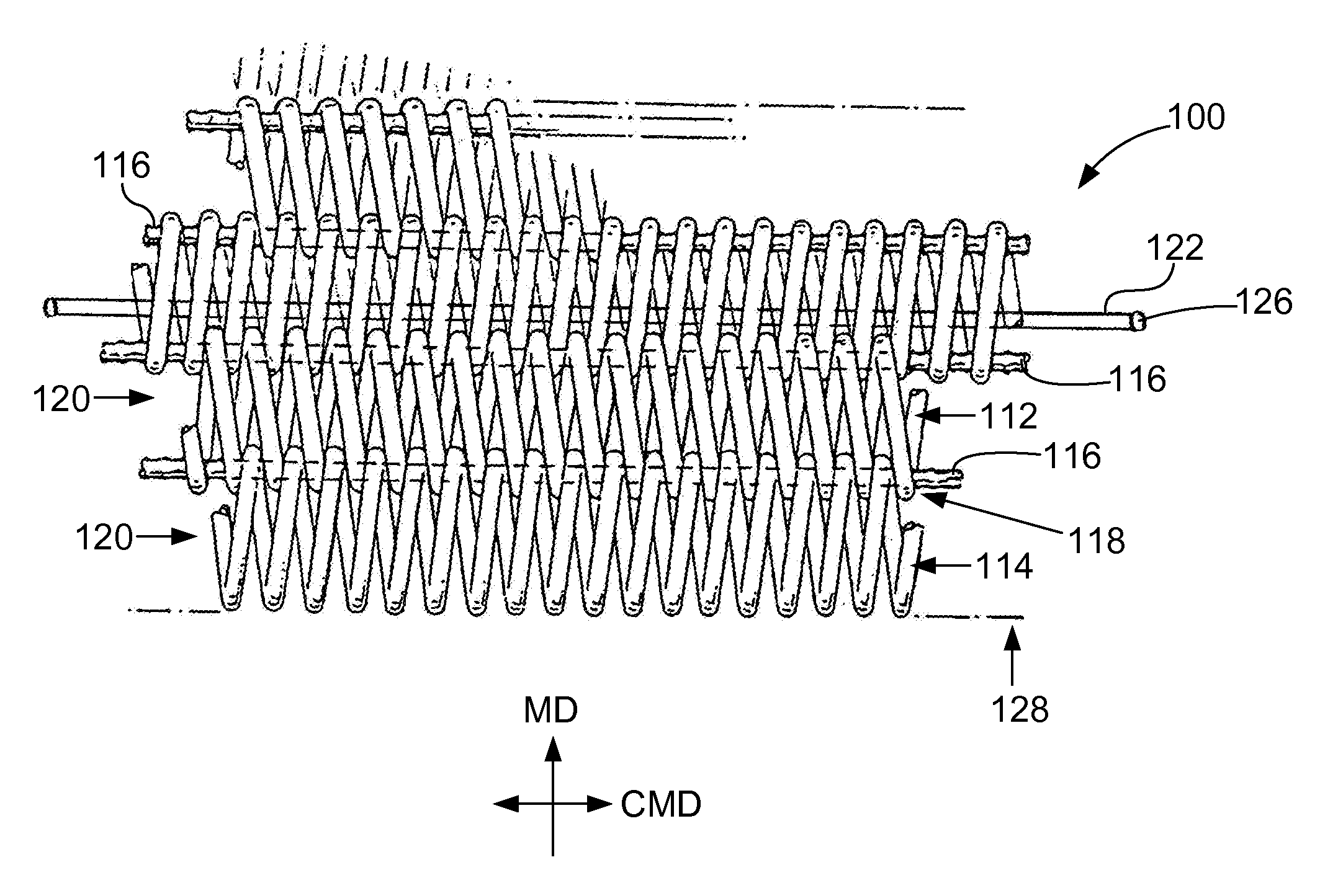
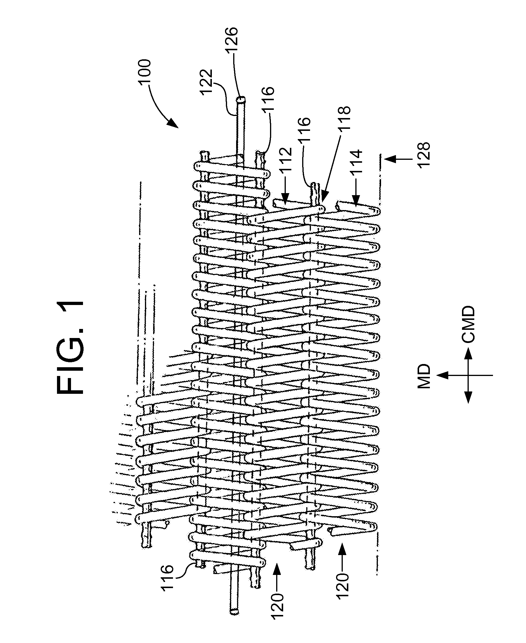
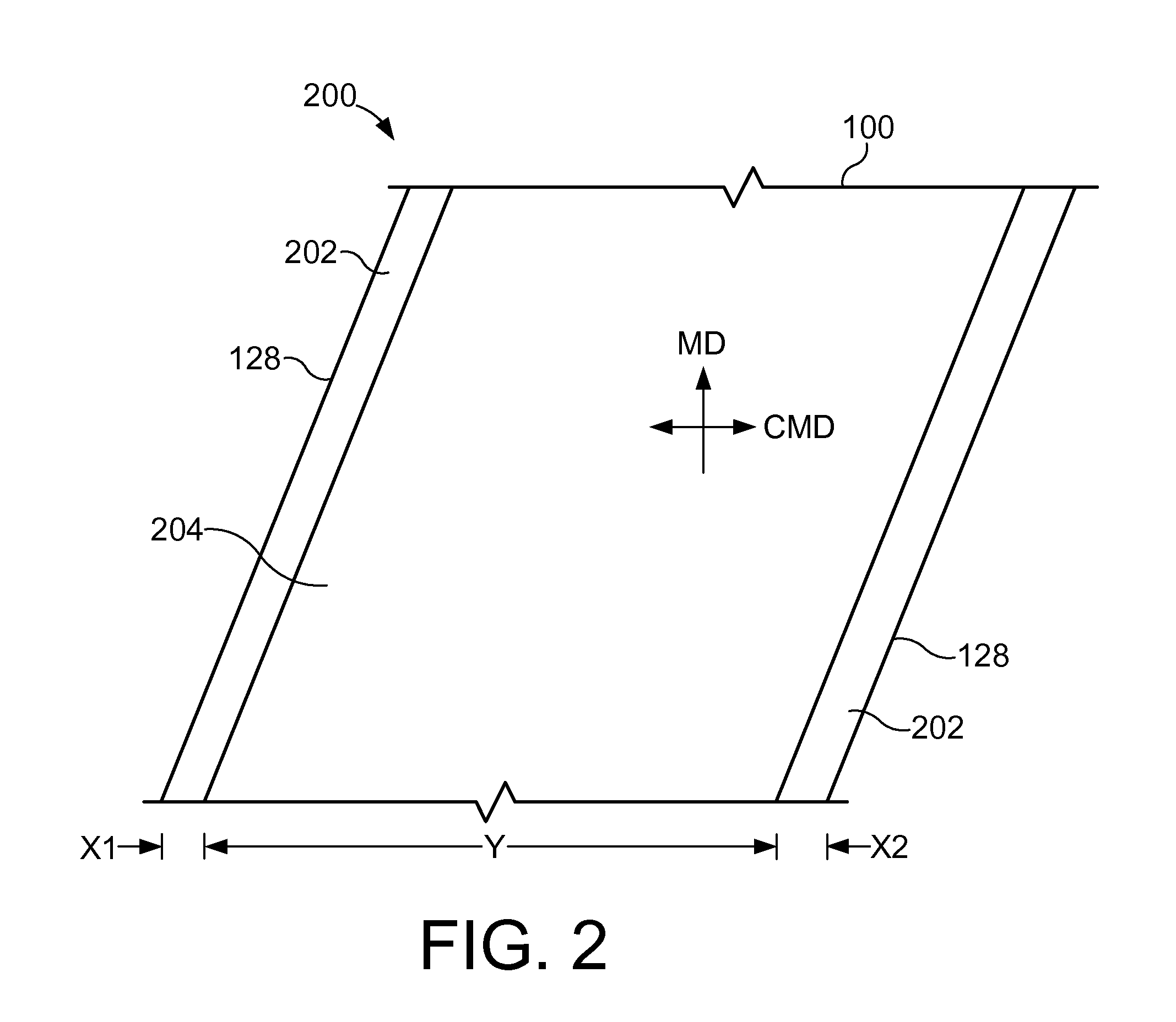
- Description
- Claims
- Application Information
AI Technical Summary
Benefits of technology
Problems solved by technology
Method used
Image

Examples
example 1
[0037]A non-woven fabric was manufactured for a corrugator machine and was constructed using a 0.90 mm diameter polyester spiral and 0.90 mm diameter hinge pin. It was stretched and heat set at 48 pli and 210° C. After that it was measured, and electrostatic control yarns of 0.52 mm diameter (nylon impregnated with carbon) were inserted into the spirals. The fabric was cut to finished size for the customer's corrugator machine, and then edge coated for 1″ on each lateral edge with a conductive edge coating in the form of a conductive carbon impregnated synthetic rubber. A traction coating of silicon was applied to the area adjacent and between the conductive edge coatings, covering the remainder of the base fabric and extending above the base fabric a distance of approximately 2 to 6 mm. The silicon rubber compound was then heat cured at 175° C. at 48 pli.
PUM
| Property | Measurement | Unit |
|---|---|---|
| Temperature | aaaaa | aaaaa |
| Temperature | aaaaa | aaaaa |
| Thickness | aaaaa | aaaaa |
Abstract
Description
Claims
Application Information
 - R&D
- Intellectual Property
- Life Sciences
- Materials
- Tech Scout
- Unparalleled Data Quality
- Higher Quality Content
- 60% Fewer Hallucinations
Browse by: Latest US Patents, China's latest patents, Technical Efficacy Thesaurus, Application Domain, Technology Topic, Popular Technical Reports.
© 2025 PatSnap. All rights reserved.Legal|Privacy policy|Modern Slavery Act Transparency Statement|Sitemap|About US| Contact US: help@patsnap.com